Machine Generated Data
Tags
Color Analysis
Categories
Imagga
| text visuals | 100% | |
Captions
Microsoft
created on 2018-03-22
| a close up of text on a white background | 75% | |
| a close up of text on a black background | 68.9% | |
| a close up of text on a white surface | 68.8% | |
OpenAI GPT
Created by gpt-4 on 2025-03-07
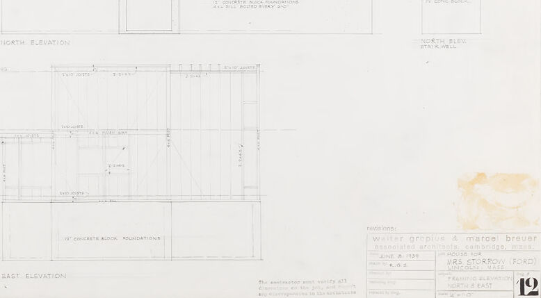
The image displays a set of architectural drawings, including detailed elevations of a building. On the left side of the sheet, the "North Elevation" is outlined, while the "East Elevation" sits along the bottom. The drawings include various notes and dimensions denoting the layout and size of different building elements, such as windows, walls, and floors. The components are carefully labeled (e.g., "2'-8" CONC. BLOCK," "2nd FLOOR JOISTS," "1st/2nd FLOOR," etc.).
You can see annotations regarding the construction and materials, like "4" CONCRETE BLOCK FOUNDATIONS" and "8" HOLLOW BLOCKS." There are also reference lines showing different levels, such as "BASEMENT FLOOR," "1ST FLOOR," and "2ND FLOOR," including an indication of the high water table. Another section of the drawing indicates a stairwell for the "North Elev."
On the right-hand side of the paper, you also notice some text indicating that these are revisions with a date ("JUNE 2, 1939") along with the name of an "A. MARCEL BREUER," who might be the architect or designer involved with this plan. Below that, it lists the building name, "House for Mrs. Story (Ford)," and the location which appears to be Cambridge, Mass. Lastly, there's an indication of the sheet number at the bottom right corner, which reads "NO. 5."
The overall condition of the sheet suggests a degree of wear and aging, marked by some discoloration in the bottom right corner, perhaps from water damage or handling over time.
Created by gpt-4o-2024-05-13 on 2025-03-07
This image is a technical architectural drawing depicting the north and east elevations of a building project for Mrs. Storrow (Ford). The drawing includes detailed measurements and annotations outlining the different sections and materials to be used in the construction. Key elements shown are:
- The north and east elevations are represented with precise dimensions, labeling different floors such as the basement, first floor, and second floor.
- The drawing indicates various structural components like the 2" x 10" joists, the stud walls, and subs headers.
- The foundation details specify a 12" concrete block foundation with a steel-supported girder.
- The stairwell on the north elevation is separately detailed.
- The architectural drawing has a title block at the bottom right corner with information: it is a project by Walter Gropius and Marcel Breuer, associated architects from Cambridge, Massachusetts, and dated June 8, 1939.
- The bottom right corner also features a unique identifier for the drawing set, labeled as "S.I. No. 12."
This detailed drawing serves to guide the construction, ensuring that all structural aspects conform to the design specifications provided by the architects.
Anthropic Claude
Created by claude-3-haiku-20240307 on 2024-12-29
The image appears to be a set of architectural plans or technical drawings for a building. It shows the north elevation, east elevation, and floor plans for what seems to be a residential or small commercial structure. The drawings include detailed dimensions, annotations, and specifications, suggesting these are construction or engineering plans. There are no identifiable human figures or faces visible in the image.
Created by claude-3-opus-20240229 on 2024-12-29
The image shows an architectural drawing or blueprint for what appears to be the north elevation of a building. The blueprint contains various dimensioned rectangles representing different sections and floors of the north-facing facade. Annotations and measurements are included to specify window sizes, floor heights, and other architectural details. The drawing has a simple, technical style typical of architectural plans and elevations used in building design and construction.
Created by claude-3-5-sonnet-20241022 on 2024-12-29
This image shows architectural elevation drawings, specifically the North and East elevations of what appears to be a residential building. The drawings are technical in nature, showing various floor levels including the basement floor, first floor, and upper floors. The details are drawn in a simple line-work style typical of architectural drawings, with measurements and annotations included. The elevations indicate features like concrete block foundations and various structural elements. The drawing appears to be from a professional set of architectural plans, with title blocks and drawing numbers visible in the bottom right corner. The drawings are primarily in black and white and appear to be done on drafting paper.
Meta Llama
Created by us.meta.llama3-2-11b-instruct-v1:0 on 2025-03-14
The image presents a technical drawing of a house, specifically a floor plan, with the title "EAST ELEVATION" and "NORTH ELEVATION" at the bottom left and right corners, respectively. The drawing is divided into two sections, each representing a different elevation of the house.
Key Features:
- Title: "EAST ELEVATION" and "NORTH ELEVATION"
- Drawing Sections: Two sections, each representing a different elevation of the house
- Labels: Various labels throughout the drawing, including:
- "NORTH ELEVATION"
- "EAST ELEVATION"
- "WALLS"
- "WINDOWS"
- "DOORS"
- "FIREPLACE"
- "STAIRWELL"
- "CONCRETE BLOCK FOUNDATIONS"
- "CONCRETE BLOCK FOUNDATIONS"
- Measurements: Various measurements are provided throughout the drawing, including:
- Room dimensions
- Door and window sizes
- Stairwell dimensions
- Scale: The drawing is scaled to 1/4 inch = 1 foot
- Date: The drawing was created on June 2, 1935
- Permits: The drawing was prepared by Walter Graphics & Marcel Breuer, and it is signed by Mrs. Storroy (Ford)
Summary:
The image presents a technical drawing of a house, specifically a floor plan, with the title "EAST ELEVATION" and "NORTH ELEVATION" at the bottom left and right corners, respectively. The drawing is divided into two sections, each representing a different elevation of the house, and includes various labels, measurements, and a scale. The drawing was created on June 2, 1935, and is signed by Mrs. Storroy (Ford).
Created by us.meta.llama3-2-90b-instruct-v1:0 on 2025-03-14
The image presents a technical drawing of the floor plan for a house, showcasing its architectural design and layout. The drawing is divided into two sections: the top section displays the north elevation, while the bottom section illustrates the east elevation.
North Elevation:
- The north elevation features a rectangular shape with a flat roof.
- The front facade includes a central entrance door flanked by two windows on either side.
- Above the entrance door, there is a small window that provides natural light to the interior.
- The exterior walls are constructed from concrete blocks, as indicated by the notation "12" CONCRETE BLOCK FOUNDATIONS" in the bottom-right corner of the drawing.
East Elevation:
- The east elevation also has a rectangular shape with a flat roof.
- The side facade features a row of windows along the top half of the wall, providing ample natural light to the interior.
- Below the windows, there is a door that leads to the exterior.
- Similar to the north elevation, the exterior walls are made of concrete blocks, as noted in the bottom-right corner of the drawing.
Additional Details:
- In the bottom-right corner of the drawing, there is a notation that reads "12" CONCRETE BLOCK FOUNDATIONS," indicating the type of material used for the foundation.
- The drawing also includes a scale bar at the bottom, which allows viewers to measure the dimensions of the house accurately.
- The overall design of the house appears to be modern and minimalist, with clean lines and simple shapes.
In summary, the image presents a detailed technical drawing of a house's floor plan, showcasing its architectural design and layout. The drawing highlights the use of concrete blocks for the exterior walls and provides a clear understanding of the house's dimensions and features.
Amazon Nova
Created by amazon.nova-lite-v1:0 on 2025-01-10
The image is a detailed architectural drawing of a building's structural layout, focusing on the east and north elevations. The drawing includes multiple sections labeled with dimensions and materials. The top section shows the basement floor with a concrete block foundation, while the middle section details the first floor with concrete block foundations and a basement floor. The bottom section outlines the second floor with similar construction details. The east elevation provides a vertical view of the building's exterior, while the north elevation shows a horizontal view. The drawing also includes annotations for revisions and verifications, indicating that it is a working document used in the construction process.
Created by amazon.nova-pro-v1:0 on 2025-01-10
The image shows a drawing of a building structure, probably a house. It is drawn on a white sheet of paper. It has several sections, including the basement floor, the first floor, and the second floor. The basement floor has a concrete block foundation. The first floor has a ceiling, and the second floor has a ceiling and a wall. The drawing also includes the north and east elevations of the building.
Text analysis
Amazon