Machine Generated Data
Tags
Color Analysis
Categories
Imagga
| text visuals | 98.7% | |
| paintings art | 0.8% | |
| nature landscape | 0.2% | |
| food drinks | 0.2% | |
Captions
Microsoft
created on 2018-03-22
| a close up of text on a whiteboard | 82.3% | |
| close up of text on a whiteboard | 80.4% | |
| a close up of a whiteboard | 79% | |
OpenAI GPT
Created by gpt-4 on 2025-03-07
You've provided an image showing a technical drawing or architectural plan. The drawing includes various labeled elements with dimensions, suggesting it is a detailed design for a part of a building or a piece of equipment. There are annotations and measurements specifying distances and materials, including notes about joints and sections. In the bottom right corner, there is text regarding revisions with dates and a title block indicating the project, draftsperson or architect, client, and other relevant details. This is typical of professional architectural or engineering drawings used to guide construction or manufacturing. The drawing appears quite faint, likely due to the lightness of the pencil or the ink used, or it may be due to the age of the document. The image has areas that are smudged, perhaps from use or handling, and there's a stamp or logo in the lower-right corner, which is common for official documents to indicate approval or project status.
Created by gpt-4o-2024-05-13 on 2025-03-07
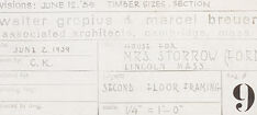
This image depicts an architectural blueprint or technical drawing of a structure's second floor framing plan. The drawing includes details such as joist placements, specific sections labeled with measurements, and construction notes. To the right, there is a detailed section labeled "SECTION A-A" that shows additional structural details, including measurements and material specifications. The bottom right corner contains a title block with information about the project, including the names of the architects (Walter Gropius and Marcel Breuer), the client's name (Mrs. Storrow), the date (June 12, 1939), the project number, the scale (one-quarter inch to one foot), and a note that revisions were made on June 14, 1939. Additionally, there is text under the title block indicating that the contractor must verify all dimensions on site and report any discrepancies to the architects. The overall design appears to be precise and detailed to guide the construction process accurately.
Anthropic Claude
Created by claude-3-haiku-20240307 on 2024-12-30
This image appears to be an architectural drawing or blueprint. It contains detailed technical specifications, measurements, and annotations related to the construction of a building or structure. The image does not contain any human faces or identifiable individuals, and focuses solely on the technical details of the design.
Created by claude-3-opus-20240229 on 2024-12-30
The image shows a technical drawing or blueprint of what appears to be a floor plan for a building or structure. The drawing includes various rectangular and square shapes connected by lines, likely representing rooms, walls, doorways and other architectural elements. Measurements and labels are written throughout the blueprint providing specifications and details about the layout and dimensions. The drawing is done on grid paper in a faded black ink, giving it a vintage or aged appearance. A small number "9" is printed in the bottom right corner of the blueprint.
Created by claude-3-5-sonnet-20241022 on 2024-12-30
This appears to be an architectural drawing or blueprint showing a cross-section view of a building or structure. It's a technical drawing with various measurements and annotations, drawn in a minimalist style with thin lines. The drawing shows structural details, including what appears to be floor framing and a stair well. There are dimension lines and notes scattered throughout the drawing, and it has a title block in the lower right corner. The drawing is primarily in black and white, with a very light, clean background typical of architectural drawings. This appears to be a professional construction document that would be used by builders or contractors to understand the structural details of the project.
Meta Llama
Created by us.meta.llama3-2-11b-instruct-v1:0 on 2025-03-13
The image presents a technical drawing of a building, likely created by an architect or engineer. The drawing is rendered in pencil on white paper and features a detailed floor plan with various rooms and spaces labeled. The top section of the drawing is dedicated to the building's exterior, while the bottom section focuses on the interior layout. **Key Features:** * **Exterior:** The top section of the drawing depicts the building's exterior, including its dimensions, windows, doors, and other architectural features. * **Interior:** The bottom section of the drawing shows the building's interior layout, including the location of rooms, corridors, and other spaces. * **Labels:** The drawing includes labels for each room and space, providing a clear understanding of the building's layout and functionality. * **Measurements:** The drawing includes measurements for each room and space, allowing for precise construction and renovation work. * **Annotations:** The drawing includes annotations and notes from the architect or engineer, providing additional context and information about the building's design and construction. **Purpose:** The purpose of this technical drawing is to provide a detailed and accurate representation of the building's design and layout. It is likely used by architects, engineers, contractors, and other professionals involved in the building's construction or renovation. **Conclusion:** Overall, this technical drawing provides a comprehensive and detailed representation of the building's design and layout. Its precision and accuracy make it an essential tool for anyone involved in the building's construction or renovation.
Created by us.meta.llama3-2-90b-instruct-v1:0 on 2025-03-13
The image depicts a technical drawing of a building's floor plan, likely created by an architect or designer. The drawing is presented in black and white, with various lines, symbols, and text that provide detailed information about the building's layout and design. **Key Features:** * **Floor Plan:** The central part of the image shows a floor plan, which appears to be a single-story building with several rooms and corridors. * **Room Labels:** Each room is labeled with a number or letter, indicating its purpose or function. * **Door and Window Locations:** The locations of doors and windows are marked on the plan, along with their sizes and orientations. * **Stairwell:** A stairwell is visible in the center of the plan, connecting the different levels of the building. * **Notes and Annotations:** Throughout the plan, there are notes and annotations that provide additional information about the design, such as material specifications, dimensions, and construction details. * **Scale:** A scale is provided in the bottom-right corner of the image, allowing viewers to measure distances and sizes accurately. * **Revision History:** A revision history is listed in the bottom-right corner, indicating the date and version number of the drawing. **Overall Impression:** The image suggests that the building is a commercial or institutional space, given the presence of multiple rooms and corridors. The level of detail in the drawing implies that it was created for construction or renovation purposes, rather than simply for conceptual design. The use of technical symbols and notation systems indicates that the drawing was intended for professionals in the field, such as architects, engineers, or contractors.
Amazon Nova
Created by amazon.nova-lite-v1:0 on 2025-02-25
This image is a technical drawing or blueprint, likely related to construction or architecture. It features a grid-like pattern with various lines, numbers, and annotations. The drawing appears to be a section or elevation view of a structure, possibly a building or a part of a building. The grid is divided into sections, with each section containing different measurements and details. The drawing includes annotations such as "STAIN WELL," "LIFTING 4X3," "AND STORE SECURELY," and "SCREWED TO FRAME," which suggest instructions or specifications for the construction process. There are also references to "REVISIONS," "JUNE 15, 1969," and "TIMBER SIZES SECTION," indicating that this is a revised version of the drawing with specific dimensions and materials mentioned. The bottom right corner of the drawing contains a table with information about the contractor, architect, and other relevant details. The table includes the names of the contractor, architect, and associated personnel, as well as dates and measurements related to the project. Overall, this image represents a technical drawing or blueprint used in the construction or architectural industry to provide detailed instructions and specifications for a specific project.
Created by amazon.nova-pro-v1:0 on 2025-02-25
The image is a technical drawing of a section of a building, likely a floor plan or a structural detail. It is rendered in black and white, with various annotations and measurements. The drawing appears to be a detailed architectural blueprint, showing the layout of a space, possibly a room or a section of a building. The annotations include dimensions, material specifications, and construction details. The drawing is labeled with a section name, possibly indicating a specific part of the building. There are also notes about the scale of the drawing and the date of the revision. The image is a professional architectural document used for construction or renovation purposes.
Text analysis
Amazon