Machine Generated Data
Tags
Color Analysis
Feature analysis
Amazon

| Document | 64.9% | |
Categories
Imagga
| text visuals | 100% | |
Captions
Microsoft
created on 2018-03-22
| a close up of text on a white background | 82.1% | |
| a close up of text on a black background | 78.3% | |
| a close up of text on a white surface | 78.2% | |
OpenAI GPT
Created by gpt-4 on 2025-03-08
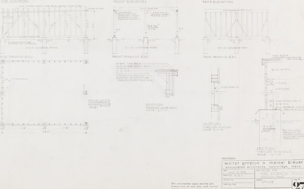
This image depicts a collection of architectural drawings. These drawings show various elevations and sectional details associated with a building project. On the left side of the image, you can see side elevations and a side framing elevation, showing the side view of the structure with measurements and structural details like where concrete posts would be placed. The center of the image shows a front elevation and a front framing elevation. Similarly, these provide a view of the building's front, including door placement, and again highlight structural components and measurements. On the right side of the image is a rear elevation and a rear framing elevation, offering the same type of detail but for the back side of the building. Below these elevations, there are additional detailed sections providing close-up views and cross-sections of specific architectural elements such as a through-door head and a window section, among others. Each drawing is carefully annotated with precise measurements, material specifications, and construction notes, which would inform construction professionals about the requirements for building. There's also a note indicating revisions by Walter Gropius & Marcel Breuer, associated architects from Cambridge, Massachusetts, which suggests that the building design has historical significance, as both Gropius and Breuer are notable figures in modern architecture. At the bottom, there's also a text field mentioning that the contractor must verify all dimensions on the job, and any discrepancies are to be reported to the architect's office, stressing the importance of accuracy in the construction process.
Created by gpt-4o-2024-05-13 on 2025-03-08
This image appears to be a detailed architectural blueprint or technical drawing for the construction of a garage. The blueprint includes several sections, elevations, and detailed notes regarding construction materials, dimensions, and structures. Here are the main sections visible in the drawing: 1. **Front Elevation:** Shows the front view of the garage, specifying details such as roofing material (5/8" x 4" jointed T&G horizontal siding) and structural elements like posts and concrete. 2. **Rear Elevation:** Displays the back view of the garage with similar detailing on materials and structural components. 3. **Side Elevation:** Provides a side view, highlighting elements like the boarding and framing post details. 4. **Side Framing Elevation:** A more intricate view focused on the framing details of the side wall, showing the placement and type of beams and posts (e.g., 2"x 11" concrete posts). 5. **Rear Framing Elevation:** Similar to the side framing elevation but showing the detailed structure of the rear side. 6. **Front Framing Elevation:** Detailed look at the framing structure of the front facade, including elements like doors or windows. 7. **Sections:** Several sectional views explain specific elements in greater detail: - Section through door head - Section through side walls - Section through window, specifying dimensions and materials. 8. **Plan View (Floor Plan):** Depicts a top-down view of the garage floor layout, showing dimensions and the relative placement of structural beams, posts, and other elements like the garage door. 9. **Construction Notes:** Technical details, such as the size and type of wood (e.g., 2x5" rafters, 1/2" plywood sheathing), and construction instructions. Additional notes on necessary revisions and instructions for contractors are included. The lower part of the blueprint credits the architects with names "Walter Gropius & Marcel Breuer," and specifies the project as a garage for a client labeled "Mrs. McSorrow (Ford)" located in Lincoln, Massachusetts. There are also standard disclaimers and revision notes, ensuring the contractor verifies all dimensions on the job site.
Anthropic Claude
Created by claude-3-haiku-20240307 on 2024-12-30
This image appears to be an architectural blueprint or technical drawing. It contains detailed plans, elevations, and sections for some kind of structure or building. The drawing includes measurements, notes, and technical specifications, indicating it is a set of construction documents. Without being able to identify any individuals, the image appears to be a professional technical drawing meant to guide the construction or renovation of a particular building or structure.
Created by claude-3-opus-20240229 on 2024-12-30
The image shows architectural drawings and plans for a building labeled "Walter Gropius & Marcel Breuer Associated Architects Cambridge, Mass." The drawings include front, rear, and side elevations of the building showing the structure from different angles. There are also detailed sections and plans depicting the interior layout and construction of the building across multiple floors. Various construction notes and dimensions are included on the technical drawings. Based on the architects listed, this appears to be plans for a Modernist building designed by the renowned Bauhaus architects Walter Gropius and Marcel Breuer.
Created by claude-3-5-sonnet-20241022 on 2024-12-30
This is an architectural drawing/blueprint showing various elevations and sections for a garage design. The drawing includes side, front, and rear elevations, along with detailed framing elevations for each view. There are also specific sections showing construction details for door heads, windows, and side walls. The plans include concrete posts, framing details, and precise measurements throughout. The drawing is dated July 15, 1940, and was created by Walter Gropius & Marcel Breuer, Associated Architects from Cambridge, Massachusetts. It appears to be drawing number 27 in a set and includes space for revisions at the bottom. The drawing uses standard architectural conventions and shows construction specifications with careful attention to structural details and dimensions.
Meta Llama
Created by us.meta.llama3-2-11b-instruct-v1:0 on 2025-03-15
The image presents a detailed architectural plan for a house, featuring a comprehensive layout of the structure's various components. The plan is divided into sections, each labeled with specific details such as side elevation, front elevation, rear elevation, and section through door head. The plan also includes measurements and notes, providing a clear understanding of the design. **Key Features:** * **Side Elevation:** The side elevation section shows the exterior wall of the house, including the location of windows and doors. * **Front Elevation:** The front elevation section displays the front facade of the house, highlighting the entrance and any notable features such as a porch or balcony. * **Rear Elevation:** The rear elevation section illustrates the back of the house, including any outdoor spaces like a patio or deck. * **Section Through Door Head:** This section provides a detailed view of the door frame and surrounding walls, offering insight into the construction and materials used. * **Measurements and Notes:** The plan includes various measurements and notes, which provide additional context and clarity to the design. **Design Elements:** * **Windows and Doors:** The plan shows the location and size of windows and doors, allowing for a clear understanding of the layout and functionality of the house. * **Exterior Walls:** The exterior walls are depicted in detail, including the type of material used and any notable features such as brick or stone. * **Roof:** The roof is shown in relation to the rest of the house, with notes on the type of roofing material used and any relevant details. * **Interior Spaces:** Although not explicitly shown, the plan implies the existence of interior spaces such as living rooms, bedrooms, and kitchens, which are likely to be included in the overall design. **Conclusion:** The architectural plan presented in the image provides a comprehensive overview of the house's design, including its layout, features, and materials. The detailed sections and measurements offer a clear understanding of the structure's components and functionality, making it an essential tool for architects, builders, and homeowners alike.
Created by us.meta.llama3-2-90b-instruct-v1:0 on 2025-03-15
The image presents a detailed architectural drawing of a garage, showcasing various elevations and sections. The drawing is divided into several sections, each providing a unique perspective on the garage's design. **Elevations:** * **Side Elevation:** This section displays the garage's side view, highlighting its height, width, and door placement. * **Front Elevation:** The front elevation shows the garage's facade, including the door, windows, and any exterior features. * **Rear Elevation:** The rear elevation provides a view of the garage's backside, which may include additional doors, windows, or other features. **Sections:** * **Section Through Door Head:** This section cuts through the garage door, revealing the door's frame, hinges, and any other details. * **Section Through Window:** This section cuts through a window, showing its frame, glass, and any other features. * **Section Through Sidewalls:** This section cuts through the garage's sidewalls, revealing the wall's construction, insulation, and any other details. **Additional Details:** * **Scale:** The drawing includes a scale, allowing viewers to accurately measure the garage's dimensions. * **Notes:** Scattered throughout the drawing are notes and annotations, providing additional information about the garage's design and construction. * **Revisions:** The drawing includes a revisions section, which lists any changes made to the original design. Overall, this architectural drawing provides a comprehensive view of the garage's design, including its elevations, sections, and additional details. It serves as a valuable resource for architects, builders, and homeowners looking to construct or renovate a garage.
Amazon Nova
Created by amazon.nova-pro-v1:0 on 2025-01-12
The image is a technical drawing of a house's architectural plans. It is divided into three sections, each showing a different elevation of the house: the side elevation, front elevation, and rear elevation. Each section includes detailed measurements, structural elements, and annotations. The side elevation shows the height and width of the house, with notes on the materials and construction details. The front elevation displays the facade, including windows, doors, and other architectural features. The rear elevation provides a view of the back of the house, highlighting the garage and other structural elements. The drawing also includes sections through the door head and window, providing a cross-sectional view of the house's construction. The plans are meticulously detailed, with measurements and notes that guide the construction process. The drawing is attributed to Walter Gropius & Marcel Breuer, Associated Architects, Cambridge, Mass., indicating the professional and precise nature of the design.
Created by amazon.nova-lite-v1:0 on 2025-01-12
This is an architectural drawing of a garage. The drawing includes the side, front, and rear elevations, as well as sections through the doorhead and through the window. The garage is made of concrete and metal framing, with a roof made of metal sheets. The drawing also includes notes and specifications for the construction of the garage, such as the dimensions of the concrete posts and the type of metal used for the framing. The drawing is signed by Walter Gropius and Marcel Breuer, who were associated architects for the project.
Text analysis
Amazon