Machine Generated Data
Tags
Color Analysis
Feature analysis
Amazon

| Document | 78.6% | |
Categories
Imagga
| text visuals | 100% | |
Captions
Microsoft
created on 2018-03-22
| a close up of text on a whiteboard | 70.7% | |
| a close up of a whiteboard | 69.5% | |
| close up of text on a whiteboard | 68% | |
OpenAI GPT
Created by gpt-4 on 2025-03-09
The image appears to be an architectural drawing or blueprint featuring a variety of diagrams and notes related to a construction project. There are several detailed sections of what seems to be a building component, such as "DETAILS OF L.R. COL. BASE" and "L.R. COL. CAP". These labels suggest the drawings are focused on column details, both at the base and the cap. There is a collection of linear diagrams with dimensions, as well as some more geometric figures such as circles that seem to represent cross-sections. Annotations accompany the diagrams, indicating dimensions in inches and feet, and specifying materials like "3/8" expansion bolt," "4" concrete floor," and "concrete fill." At the bottom left corner, there's a table with revisions, citing the names "Walter Gropius & Marcel Breuer Associated Architects, Cambridge, Mass." with dates that are too blurry to read. This information attributes the drawing to two renowned architects, indicating that the blueprint might be for an important architectural or construction project. The drawing is technical in nature, granulometric and meant for professionals like architects, engineers, or builders. It has been marked up with notes for changes and the drafting style is precise and to scale, which is typical for architectural blueprints.
Created by gpt-4o-2024-05-13 on 2025-03-09
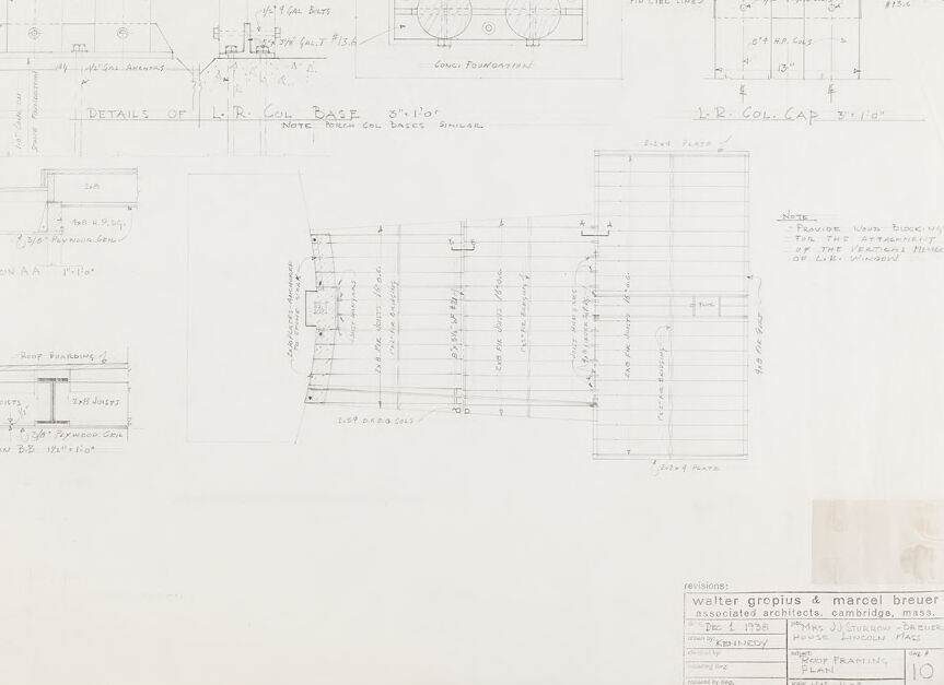
This is an architectural plan detailing several structural elements, primarily focusing on the "I.B.R. Column Base" and "I.B.R. Column Cap." The drawing includes various views and sections, with precise measurements and notations. Here's a breakdown of the components illustrated: 1. **Top Left Section**: Detailed drawing of the column base, showing various measurements and construction specifications. The image includes dimensions, materials, and mounting specifications, indicating the use of reinforced concrete and positioning of bolts. 2. **Top Center to Top Right Section**: Elevation views showing the positioning, dimensions (including sizes like 1'-0" and 2'-0"), and structural components related to the column cap, along with notes on alignment and material requirements like bolts and concrete. 3. **Center Left Section**: Cross-section labeled as “SECTION A-A,” depicting the roof boarding and joist configuration with specific notes on plywood spacing. 4. **Center Section**: An overhead view of the column base plan, labeled "PLAN," displaying layout, dimensions, and detailed annotations for proper assembly, including placement of bolts and other reinforcements. 5. **Bottom Left Section**: Another cross-section labeled “SECTION B-B,” similar to Section A-A, but detailing additional structural elements, including roof boarding, 2x8 joists, and plywood spacings. 6. **Bottom Right Section**: An extensive floor framing plan with detailed grid lines, dimensions, and annotations, emphasizing the provision of timber blocking at specified intervals to support the vertical members of the partitions. **General Notes**: - Various notes such as "NOTE: Provide timber blocking for the attachment of the vertical members of the I.B.R. partitions" add instructions to ensure proper construction. - The title block at the bottom right indicates the architects involved (Walter Gropius & Marcel Breuer), the project details (for Mr. and Mrs. J.J. Shonkoff), and the drawing’s content (floor framing plan) with a date of Dec 1, 1950, and scale information. This plan combines several views and sections to give a comprehensive representation necessary for construction, focusing on the intricate details of the column base, caps, and associated structural elements.
Anthropic Claude
Created by claude-3-haiku-20240307 on 2024-12-31
The image appears to be an architectural blueprint or technical drawing. It contains various sketches, measurements, and annotations that seem to be related to the design or construction of some kind of structure or object. The drawing includes details like dimensions, cross-sectional views, and notes, but does not appear to depict any human faces or identifiable individuals. The overall content of the image is focused on the technical aspects of the design rather than any human subjects.
Created by claude-3-5-sonnet-20241022 on 2024-12-31
This is an architectural drawing/blueprint showing various technical details and specifications. The drawing appears to be focused on foundation and base details, with multiple cross-sectional views and measurements. It includes details labeled "L.R. COIL BASE" and various sectional drawings marked as "SECTION A-A" and "SECTION B-B". The drawing contains precise measurements and notations throughout, typical of professional architectural documentation. At the bottom of the sheet, there's a title block indicating this is from Walter Gropius & Marcel Breuer's architectural firm in Cambridge, Massachusetts. The drawing appears to be hand-drafted, which was common for architectural drawings of that era, and shows various construction details including foundation elements and structural components.
Meta Llama
Created by us.meta.llama3-2-11b-instruct-v1:0 on 2025-03-16
The image is a technical drawing for a building project, featuring a detailed plan and elevation of the structure. The drawing includes various sections, including a section A-A, section B-B, section C-C, and section D-D, which provide a comprehensive view of the building's design. **Key Features:** * **Elevation:** The elevation of the building is shown, providing a clear view of the exterior design. * **Section A-A:** This section shows the building's interior layout, including the location of walls, doors, and windows. * **Section B-B:** This section provides a detailed view of the building's foundation, including the location of footings and piers. * **Section C-C:** This section shows the building's roof design, including the location of rafters and roofing materials. * **Section D-D:** This section provides a detailed view of the building's exterior walls, including the location of windows, doors, and other architectural features. **Additional Details:** * **Scale:** The drawing is scaled at 1/4" = 1'-0", indicating that each quarter inch on the drawing represents one foot in real life. * **Materials:** The drawing includes notes on the materials to be used for the building's construction, including wood, steel, and concrete. * **Dimensions:** The drawing includes precise dimensions for each component of the building, ensuring accurate construction. **Conclusion:** The technical drawing provides a comprehensive and detailed plan for the building project, including elevations, sections, and materials. The drawing is well-organized and easy to read, making it a valuable tool for architects, engineers, and contractors involved in the project.
Created by us.meta.llama3-2-90b-instruct-v1:0 on 2025-03-16
This image depicts a technical drawing, likely an architectural plan, featuring various sections and details of a building's design. The drawing is rendered in pencil on white paper, with handwritten notes and measurements throughout. **Key Features:** * **Title:** "DETAILS OF L.R. COL. BASE" is written at the top center of the page. * **Sections:** The drawing includes several sections, including a cross-section of a column base, a plan view of the same, and a detail of the column cap. * **Measurements:** Various measurements are noted throughout the drawing, including dimensions for the column base, cap, and surrounding structure. * **Notes:** Handwritten notes provide additional information about the design, such as the type of material used for the column base and the location of the column cap. * **Scale:** A scale is provided in the bottom-right corner of the page, indicating that the drawing is to be read at a scale of 1/4" = 1'-0". * **Revisions:** A revision block in the bottom-right corner indicates that the drawing was revised on December 4, 1968, by Walter Gropius & Marcel Breuer, Associated Architects, Cambridge, Mass. **Overall Impression:** The image presents a detailed and technical drawing of a building's design, showcasing the attention to detail and precision required in architectural planning. The use of pencil and handwritten notes adds a personal touch to the drawing, while the inclusion of measurements and scales ensures that the design can be accurately implemented.
Amazon Nova
Created by amazon.nova-lite-v1:0 on 2025-02-28
The image is a technical drawing, likely from an architectural or engineering context. It contains detailed plans and sections of a structure, possibly a building or a part of a building. The drawing includes various annotations and labels, indicating dimensions, materials, and specific design details. There are multiple views, including a plan view and section views, showing different perspectives of the structure. The drawing is labeled with "Walter Gropius & Marcel Breuer," suggesting it is related to the work of these architects. The image also includes a revision date of July 1, 1938, and mentions "House Lincoln Mac" and "ROOF FRAMING PLAN," indicating the specific project and focus of the drawing.
Created by amazon.nova-pro-v1:0 on 2025-02-28
The image is a technical drawing on a large sheet of paper, likely a blueprint or architectural plan. The drawing is composed of several sections, each depicting different aspects of a structure, possibly a building or a part of a building. The sections include detailed measurements, annotations, and labels, which are typical of architectural or engineering drawings. The text and measurements are written in a clear, legible font, and the drawing is done in black ink on a white background. The layout suggests a methodical and precise approach to the design, with each section carefully delineated and labeled. The drawing includes notes and instructions for construction, such as "Provide water blocking for the attachment of the vertical members of the L.R. Window" and "Details of R.R. COL. BASE 3'-10'." The overall appearance of the drawing indicates a professional and detailed approach to the design process.
Text analysis
Amazon