Machine Generated Data
Tags
Color Analysis
Feature analysis
Amazon
Clarifai

Clarifai
| Picture frame | 99.7% | |
Categories
Imagga
created on 2022-06-04
| paintings art | 95.7% | |
| text visuals | 2.7% | |
Captions
Clarifai
No captions written
Salesforce
Created by general-english-image-caption-blip on 2025-05-21
a photograph of a drawing of a drawing of a plan for a house
Created by general-english-image-caption-blip-2 on 2025-06-28
a drawing of a building with a plan and a drawing of the building
OpenAI GPT
Created by gpt-4 on 2024-12-07
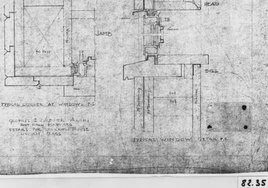
This image shows a technical drawing or blueprint of architectural details, specifically focusing on the sections of a window. The drawing includes labeled parts such as "jamb" and "head," indicating different components of the window structure. You can see various lines representing the side view and cross-sections, which are typical in architectural and engineering drawings to convey the dimensions and assembly methods of the window construction.
There are written notes and annotations that provide additional information about the design, including reference to "Details at Stenton House" and the date "March 1935." These notes suggest that the drawing relates to a specific historic building or restoration effort.
The image appears to be a photograph of the original drawing, as indicated by the white border around the drawing and the mounting in a dark frame or mat. The drawing itself shows signs of wear or aging, with scattered marks and discolorations, which is common for archival architectural documents.
Created by gpt-4o-2024-05-13 on 2024-12-07
The image shows a framed architectural drawing. The drawing includes detailed sketches and notes that appear to specify the design and construction details of a window. Some of the annotations visible in the drawing include terms like "HEAD," "JAMB," and "SILL," which are common in architectural descriptions of window elements.
The title written at the bottom of the drawing reads: "TYPICAL DETAIL AT WINDOW F.G.", and below that, there is additional text which appears to mention the names of the architects and the type of detail the drawing is specifying. The drawing is a monochromatic, hand-drawn plan and appears to be aged, suggesting it may be a historical document or an older blueprint. The frame surrounding the drawing is simple and black, with a small label at the bottom right corner displaying the number "82.85".
Anthropic Claude
Created by us.anthropic.claude-3-5-sonnet-20241022-v2:0 on 2025-06-24
This image appears to be an architectural drawing or technical diagram showing window details. It's a black and white technical sketch that shows cross-sectional views of window components, including the jamb, head, and sill sections. The drawing appears to be titled "TYPICAL WINDOW DETAILS" and shows various construction elements and measurements for window installation. The drawing is presented in what looks like an old or historical document format, with some aging or texture visible in the paper. It's framed in what appears to be a dark border, and there's a number (82.35) visible in the corner. The drawing includes detailed cross-sections that show how different parts of the window assembly fit together, which would be typical of architectural construction documents.
Created by claude-3-haiku-20240307 on 2024-12-07
The image appears to be an architectural drawing or blueprint. It shows detailed technical diagrams and sketches of a structural or mechanical design, likely for a window or some kind of construction project. The drawing contains various labeled components and measurements, indicating it is a schematic or engineering plan. The overall image has a black and white, technical illustration style.
Created by claude-3-5-sonnet-20241022 on 2024-12-07
This image shows an architectural drawing or blueprint detailing window specifications. It appears to be a technical drawing showing window cross-sections and details, with labels for different components like "HEAD," "JAMB," and "SILL." The drawing includes multiple views of what seems to be a typical window detail, showing how the window is constructed and how it fits into the wall structure. The image is in black and white and appears to be an older or historical architectural document. The drawing is mounted or framed with a dark border, and there appears to be a number "82.35" in the bottom right corner.
Meta Llama
Created by us.meta.llama3-2-11b-instruct-v1:0 on 2024-12-07
The image presents a detailed architectural drawing, likely created by a professional architect or engineer, showcasing the design and layout of a building. The drawing is presented in black and white, with a focus on precision and clarity.
Key Features:
- Title: The title of the drawing is not explicitly stated, but it appears to be a technical drawing for a building project.
- Scale: The scale of the drawing is not indicated, but it appears to be a detailed plan rather than a rough sketch.
- Layout: The drawing features a rectangular shape with a central section and two side sections. The central section appears to be a floor plan, while the side sections may represent elevations or cross-sections of the building.
- Lines and Symbols: The drawing uses a range of lines and symbols to convey information about the building's design and construction. These include:
- Solid lines: used to represent walls, floors, and other permanent features
- Dashed lines: used to represent doors, windows, and other openings
- Dotted lines: used to represent electrical or plumbing systems
- Arrows: used to indicate direction and flow
- Text: The drawing includes several lines of text, which appear to be notes and annotations made by the architect or engineer. These may include:
- Room numbers and labels
- Material specifications
- Construction details
- Numbering: The drawing is numbered "82.35" in the bottom-right corner, suggesting that it may be part of a larger collection of drawings or plans.
- Border: The drawing is surrounded by a black border, which helps to frame the image and provide context.
Overall Impression:
The image presents a detailed and technical drawing that appears to be a critical component of a building project. The use of precise lines, symbols, and text suggests a high level of accuracy and attention to detail, which is consistent with the standards of professional architectural and engineering work.
Created by us.meta.llama3-2-90b-instruct-v1:0 on 2024-12-07
This image is a black-and-white sketch of a building's floor plan, featuring a window and door. The sketch is presented in a black frame with a white mat, set against a gray background.
The sketch itself appears to be hand-drawn and includes various labels and measurements. It depicts a room with a window on the left side and a door on the right side. The window is labeled as "Typical Window at Windows" and has several measurements noted around it. The door is labeled as "Jamb" and also has measurements listed nearby.
In the bottom-right corner of the sketch, there is a small notation that reads "82.35." This may refer to a specific section or page number within a larger document or blueprint.
Overall, the image suggests that it is a technical drawing or architectural plan for a building, likely created by an architect or designer. The level of detail and precision in the sketch indicates that it was intended for use in the construction or renovation of a physical structure.
Amazon Nova
Created by amazon.nova-lite-v1:0 on 2025-02-26
The image appears to be a technical drawing or blueprint of a structure, possibly a building or a room. The drawing is in black and white and shows a floor plan or elevation view. The drawing includes various labels and annotations, such as "TYPICAL COVER AT WINDOWS", "TYPICAL WINDOW DETAIL", and "82.35". The drawing also includes dimensions and measurements, such as "4 POST" and "44". The drawing is framed by a black border, and the image has a slightly blurry quality, possibly due to the age or quality of the original document.
Created by amazon.nova-pro-v1:0 on 2025-02-26
The image shows a framed drawing with a black border. The drawing appears to be a technical blueprint or architectural plan. The drawing is in black and white, and it depicts various elements and measurements related to the construction of a building or structure. The drawing includes labels such as "HEAD," "JAM," and "SILL," which likely refer to different components or features of the structure. The drawing also includes a reference to "TYPICAL COPPER AT WINDOWS," indicating that the plan may be related to the installation of copper elements around windows. The overall image suggests that it is a detailed technical drawing used for construction or engineering purposes.
Google Gemini
Created by gemini-2.0-flash-lite on 2025-04-28
Here's a description of the image:
The image shows a framed architectural drawing, likely a blueprint or technical drawing. Here's a breakdown:
- Framing: The drawing is encased in a black frame, with a white matte border. This presentation suggests that the drawing is a piece of artwork or an archival document.
- Drawing Details: The drawing itself depicts details of window construction. It includes:
- Plan Views: Two main sections, labeled "Typical Corner At Window P.G." and "Typical Window Detail P.G." These represent cross-sectional views of how a window is constructed.
- Labels: Key components like "Jamb," "Head," and "Sill" are labeled to identify the different parts of the window frame. Other labels are used to identify dimensions and the materials used.
- Text Information: There's also handwritten text, which seems to indicate:
- Architect/Firm: "Gropius & Breuer Arch"
- Project: "Details for Yorkrow House Lincoln Mass"
- Drawing Number: "82.35" is on the lower right corner.
- Overall Impression: The drawing appears to be an older blueprint-style rendering, showing a detailed technical specification for a window design for a specific architectural project. The wear and tear on the paper suggest the age of the plan.
Created by gemini-2.0-flash on 2025-04-28
The image shows a framed architectural drawing or blueprint in black and white. The drawing is labeled with handwritten text, presumably specifying details of a "typical corner at window" and a "typical window detail." It includes sections labeled "Jamb," "Head," and "Sill," indicating different parts of the window structure. The blueprint is attributed to "Gropius & Iurber, Arch" and appears to be related to details for the "Groprow House" in "Linch. Mass." There's a numeric identification mark "82.35" visible at the bottom corner of the frame. The paper of the blueprint has a slightly aged appearance.
Mistral Pixtral
Created by us.mistral.pixtral-large-2502-v1:0 on 2025-04-28
The image is a black and white architectural drawing that appears to be a detailed blueprint for window construction. The drawing is framed and labeled with the number "82.35" in the bottom right corner.
The drawing includes two main sections:
Typical Mullion at Window Head:
- This section shows a detailed view of the mullion (a vertical bar between the panes of glass in a window) at the head (top) of the window.
- It includes measurements and labels for various components such as the "Head," "Jamb," and "Stop."
- The drawing indicates the dimensions and positioning of these elements in relation to each other.
Typical Window Detail:
- This section provides a detailed cross-sectional view of a typical window.
- It includes labels for different parts of the window such as the "Frame," "Sill," "Head," and "Jamb."
- The drawing shows how these components are assembled and their relative positions.
The drawing also includes some text at the bottom left, which reads:
"600 PILLS B LAY TREK ARCHT
WILLIAM RAYMOND
DETAIL FROM PRAIRIE HOUSE
BUILT IN 1902"
This text suggests that the drawing is a detail from a Prairie House designed by William Raymond and built in 1902. The term "Prairie House" often refers to a style of architecture popularized by Frank Lloyd Wright, characterized by horizontal lines and integration with the landscape.
Qwen
Created by Qwen/Qwen2.5-VL-7B-Instruct on 2025-07-26
The image shows a black and white architectural drawing that appears to be a technical drawing of a window detail for a specific architectural project. The drawing includes labeled sections of the window frame and its components. The labels indicate the head, jamb, and sill of the window. The drawing is annotated with dimensions and text, likely providing specific technical details such as measurements and notations for construction purposes. The text at the bottom of the drawing mentions "Typical Window Detail," suggesting that this drawing is a standard reference for a particular window design. The drawing is framed and appears to be a historical document, possibly from a collection of architectural plans.
Created by Qwen/Qwen2.5-VL-72B-Instruct on 2025-07-26
This image shows a framed architectural blueprint or construction drawing. The blueprint includes detailed technical illustrations and annotations, providing a guide for window construction.
Key Features:
Left Side - Typical Gable at Window Section:
- This section shows a cross-section of a gable (triangular roof structure) at a window.
- It includes labels for the "jamb" (the side frame of a window) and shows measurements for structural components of the gable.
Right Side - Typical Window Detail Section:
- This section provides a detailed view of a window, including the "head" (top part of the frame) and "sill" (bottom part of the frame).
- It appears to detail the structural framework and connections of the window components.
Annotations and Labels:
- There are handwritten annotations, likely design notes or specifications.
- The text includes references to the "Boy Hall, Harvard" project and is dated "Lincoln, Mass."
Condition:
- The paper appears aged, with some visible folds, stains, and wear, suggesting it is a historical or vintage drawing.
Frame and Labeling:
- The drawing is mounted and framed, with a mat board and a black frame.
- The number "82.35" appears in the bottom right corner of the mat, potentially indicating the catalog or identification number for this item.
This blueprint is likely a part of historical architectural or construction records.
Text analysis
Amazon