Machine Generated Data
Tags
Color Analysis
Feature analysis
Amazon
Clarifai

Clarifai
| Whiteboard | 74.1% | |
Categories
Imagga
created on 2018-03-22
| text visuals | 97.9% | |
| paintings art | 1.9% | |
| food drinks | 0.1% | |
Captions
Microsoft
created by unknown on 2018-03-22
| a close up of text on a white surface | 71.8% | |
| a screenshot of text | 71.7% | |
| a close up of text on a white background | 70.9% | |
Clarifai
No captions written
Salesforce
Created by general-english-image-caption-blip on 2025-05-11
a photograph of a drawing of a drawing of a kitchen
Created by general-english-image-caption-blip-2 on 2025-06-28
a drawing of a bathroom with a toilet and sink
OpenAI GPT
Created by gpt-4 on 2025-03-09
This image shows a technical drawing, most likely architectural in nature. On the left side, you see a labeled "ELEVATION" and "PLAN" indicating different views of the same design—a plan view (top-down) and an elevation view (front or side view). There are various annotations and dimensions specified, which is typical for detailed construction or manufacturing drawings.
In the center-top portion, there is a smaller annotated sketch, possibly detailing a specific component or mechanism related to the larger drawing. To the right side, labeled "SECTION," there is a cross-sectional view which provides an inside look at the structure or object, also with several annotations.
At the bottom right, there are notes indicating revisions to the document. Names are mentioned, which seem to be associated with the drawing, along with dates and other administrative details.
The drawing style suggests it might be an older document, as modern architectural and engineering drawings are often made using computer-aided design (CAD) software, and this looks hand-drafted.
Created by gpt-4o-2024-05-13 on 2025-03-09
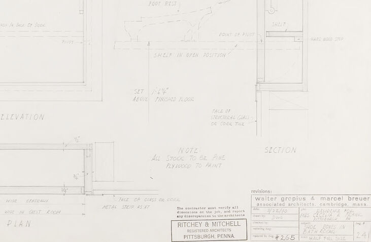
The image depicts an architectural drawing of a piece of furniture or a built-in installation, possibly a shelving unit or a closet. It includes detailed annotations and measurements indicating various views such as elevation, section, and plan.
Key elements observed in the drawing are:
- Elevation view: shows the vertical outline of the unit, with noted dimensions and positions of different parts like door, pivot points, and materials (e.g., metal).
- Section view: provides a side cutaway perspective illustrating the internal components like shelves, foot rests, and joints.
- Plan view: offers a top-down perspective with dimensions indicating the width and component placements.
Specific notes highlight construction details, such as "PLYWOOD TO PAINT," "SET ABOVE FINISHED FLOOR," and "POINT OF PIVOT." References to materials such as "METAL" and instructions for stock and assembly are also included.
The drawing is presented with a professional stamp at the bottom right, indicating it was prepared by RITCHEY & MITCHELL, registered architects based in Pittsburgh, PENNA. Additionally, the drawing credits significant architects, Walter Gropius & Marcel Breuer, showing associations with a well-known architectural firm.
The title block contains specific project information like client name, possibly referencing "Russel House" alongside other relevant project data, denoting experienced architectural input for the design detailed.
Anthropic Claude
Created by us.anthropic.claude-3-5-sonnet-20241022-v2:0 on 2025-06-25
This image appears to be an architectural drawing or blueprint showing both elevation and plan views of what seems to be a piece of furniture or built-in cabinet. The drawing is done in a technical style with precise lines and measurements. It's labeled with "ELEVATION" and "PLAN" views, and includes various notes and specifications. The drawing is credited to "Walter Gropius & Marcel Breuer" and was created by "RITCHEY & MITCHELL" from Pittsburgh, Pennsylvania. There's a note indicating "ALL STOCK TO BE PLYWOOD TO PAINT." The drawing shows detailed construction specifications including dimensions and appears to be a professional architectural document from what looks like a larger set of plans.
Created by claude-3-haiku-20240307 on 2024-12-31
This image appears to be a technical drawing or architectural plan. It contains detailed diagrams and measurements for a structure, including an elevation view, a section view, and a plan view. The drawing includes various annotations and notes, likely providing additional details and instructions. The overall layout and presentation suggest this is a design or construction document produced by an architectural or engineering firm, as indicated by the name "Ritchey & Mitchell" at the bottom of the image.
Created by claude-3-5-sonnet-20241022 on 2024-12-31
This appears to be an architectural drawing or blueprint showing various views (elevation, plan, and section) of what seems to be a display case or cabinet design. The drawing is created by Walter Gropius & Marcel Breuer, architects from Cambridge, Massachusetts, for Ritchey & Mitchell of Pittsburgh, Pennsylvania. The document includes technical details, measurements, and construction notes. There's a main elevation view showing a framed panel or case, a plan view showing the layout from above, and a section view showing the internal construction details. The drawing includes notes about materials and finishing, with one note specifically stating "ALL STOCK TO BE PINE PLYWOOD TO PAINT." The drawing appears to be professionally drafted with clean lines and proper architectural annotations and measurements.
Meta Llama
Created by us.meta.llama3-2-11b-instruct-v1:0 on 2025-03-16
The image depicts a technical drawing for a door, featuring a detailed plan and elevation view. The drawing is presented on a white sheet of paper with black text and lines, showcasing the door's dimensions and specifications.
Key Features:
- Door Dimensions: The drawing includes measurements for the door's width, height, and thickness, as well as the size of the frame and surrounding trim.
- Elevation View: The elevation view provides a side-by-side comparison of the door's front and back sides, highlighting the location of hinges, handles, and other features.
- Plan View: The plan view offers a top-down perspective of the door, illustrating its shape and layout.
- Notes and Annotations: The drawing includes notes and annotations that provide additional information about the door's design and construction, such as the type of material used and any special features or requirements.
Overall Impression:
The technical drawing appears to be a detailed and accurate representation of the door's design, suggesting that it was created by a skilled draftsman or architect. The level of detail and precision in the drawing implies that it was intended for use in a professional or commercial setting, such as a construction project or a furniture manufacturing facility.
Created by us.meta.llama3-2-90b-instruct-v1:0 on 2025-03-16
This image presents a detailed architectural drawing of a cabinet, showcasing its design and specifications. The drawing is rendered in pencil on white paper, with a focus on the cabinet's elevation and section views.
Elevation View:
The elevation view, situated on the left side of the drawing, provides a frontal perspective of the cabinet. It features a rectangular shape with a flat top and bottom, accompanied by a door that spans the entire width of the cabinet. The door is adorned with a handle positioned at the top center, while the cabinet's frame is outlined in a thin line. Additional details include measurements and notes in pencil, which offer further insight into the cabinet's design.
Section View:
The section view, located on the right side of the drawing, offers a cross-sectional perspective of the cabinet. This view reveals the cabinet's internal structure, including shelves and compartments. The section view is also accompanied by measurements and notes in pencil, providing a comprehensive understanding of the cabinet's design.
Additional Details:
In the bottom-right corner of the drawing, a small box contains information about the revisions made to the design. This includes the names of the architects involved, Walter Gropius and Marcel Breuer, as well as the date of the revisions, February 25, 1954. The box also features a note indicating that the contractor must verify all dimensions on the job site and report any discrepancies to the architect.
Overall:
This architectural drawing provides a detailed and accurate representation of the cabinet's design, including its elevation and section views. The inclusion of measurements and notes in pencil adds an extra layer of detail, making it a valuable resource for architects, designers, and contractors working on the project.
Amazon Nova
Created by amazon.nova-pro-v1:0 on 2025-02-27
The image is a blueprint of a building, specifically a section and elevation plan. It is a technical drawing that provides detailed information about the structure and layout of a building. The blueprint is divided into several sections, each providing specific information about the building's design. The section plan shows the vertical cross-section of the building, including the walls, floors, and ceilings. The elevation plan shows the front and side views of the building, including the windows, doors, and other architectural features. The blueprint also includes notes and dimensions, providing precise measurements and instructions for the construction of the building. Overall, the blueprint is a crucial tool for architects, engineers, and builders, as it provides a detailed plan for the construction of a building.
Created by amazon.nova-lite-v1:0 on 2025-02-27
The image is a detailed architectural drawing, likely from a construction or renovation project. The drawing is labeled "ELEVATION" and "SECTION" at the top, indicating that it shows both a vertical view (elevation) and a cross-sectional view of a structure. The drawing includes various annotations and dimensions, such as "12-0" CAT LEASE STAY JOINTS (FLANGE)" and "FOOT REST." There are also notes about materials, such as "METAL" and "STEEL STUD," and specific measurements like "1'-6" WIDE GENERALLY" and "3' WIDE IN GHOST ROOM." The drawing is signed by "WALTER GROPIUS & MARCEL BREULER" and includes a reference to "PITTSBURGH, PENNA," suggesting the location of the project. The drawing also has a revision number "2.265" and a date "HALF FALL 1924," indicating the version and time of the drawing.
Google Gemini
Created by gemini-2.0-flash-lite on 2025-05-09
This is an architectural drawing, likely a blueprint or technical illustration, created by Ritchey & Mitchell, registered architects in Pittsburgh, Pennsylvania. The drawing is dated March 22, 1940, and includes revisions from Walter Gropius & Marcel Breuer, associated architects, of Cambridge, Massachusetts.
The drawing presents detailed plans for a piece of furniture or built-in element, possibly a cabinet or a similar structure. The views include an elevation, section, and plan.
Here's a breakdown of the drawing's components:
- Elevation: This shows the front view of the structure, detailing the door with a "Lacite Pull" and dimensions, as well as the overall shape.
- Section: This gives a cross-sectional view of the structure, showing the internal components like a shelf, and how the door is hinged. It also displays the "1/2" CAP. CAST BRASS STAY JOINTS (FIXED)" detail.
- Plan: This presents a top-down view, displaying the shape and dimensions of the structure as it would appear in the room.
Annotations and notes provide specific details:
- The annotations label various parts such as "Shelf in back of door", "metal," "pivot".
- The "Note" section specifies that the "ALL STOCK TO BE PINE PLYWOOD TO PAINT".
- The revision section notes a reference to a "BATH ROOMS" and indicates the scale of the drawing as "HALF FULL SIZE."
Overall, the drawing is a technical document designed for construction purposes, providing all the measurements and details necessary to construct a piece of furniture or a built-in element.
Created by gemini-2.0-flash on 2025-05-09
Here's a description of the image based on the provided information:
Overall Impression:
The image is a technical architectural drawing or blueprint. It appears to be a design detail for a built-in feature, possibly a cabinet or shelf with a drop-down component, within a room. The drawing provides elevation, plan, and section views.
Specific Details:
Elevation View: Shows the front view of the feature. There's a rectangular outline labeled "METAL," likely indicating a metal surround or frame. It features a "Lacite Pull" at the top and a "shop in back of doce." The shelf at the bottom is on pivot points.
Plan View: Shows the top-down view, indicating the width ("1'-0" wide generally"). It also specifies the width ("2 wide in Grest room"). The "face of glass or cork" is mentioned.
Section View: Depicts a side cut-through view, revealing internal components. Key elements include a "foot rest," a shelf that pivots ("shelf in open position"). The location above the floor is also indicated ("set 1'-64" above finished floor"). A point of pivot and a "hard wood step" are also included.
Notes: A note specifies that "All stock to be pine plywood to paint."
Additional Details:
There are lines, labels, and dimensions throughout the drawing, providing precise measurements and specifications.
The bottom right corner includes information like the architects (Walter Gropius & Marcel Breuer), the date (3/22/10), and possibly the project name (RESIDENCE). There's also a revision box.
The architects listed are Ritchey & Mitchell, Registered Architects of Pittsburgh, Penna.
In essence, the drawing appears to be a detailed architectural specification for a custom-built element with a pivoting shelf or door mechanism, likely intended to be constructed from pine plywood and painted.
Mistral Pixtral
Created by us.mistral.pixtral-large-2502-v1:0 on 2025-05-31
The image is a detailed architectural drawing that includes various views and dimensions of a structure, likely a cabinet or a small enclosure. The drawing is divided into several sections:
Elevation View:
- This is the front view of the structure.
- It shows the overall height and width, including details such as the location of a shelf, a drawer, and a door.
- Dimensions are provided for various elements like the drawer face, shelf, and overall structure.
Section View:
- This is a vertical cross-section of the structure.
- It provides a side view showing the internal layout, including the positioning of the shelf, drawer, and door.
- Dimensions are indicated for the depth and height of internal components.
Plan View:
- This is the top-down view of the structure.
- It shows the layout from above, including the width and depth of the structure.
- Dimensions are provided for the overall width and depth, as well as the placement of internal elements.
Notes and Annotations:
- There are several notes and annotations scattered throughout the drawing.
- These notes provide additional instructions and details, such as the type of finish, the positioning of elements, and specific dimensions.
- One note specifies that all exposed surfaces are to be finished to match.
Revision History:
- The bottom right corner of the drawing includes a revision history.
- It lists the names of individuals involved in the revisions (Walter Gradius and Marcel Breuer) and the dates of the revisions.
- It also includes a reference number (#265) and a note about the scale of the drawing.
Company Information:
- The drawing is credited to "Ritchey & Mitchell, Architects, Pittsburgh, Penna."
- This indicates the architectural firm responsible for the design.
Overall, the drawing provides a comprehensive set of views and dimensions necessary for the construction or fabrication of the structure, along with detailed notes and revision history for clarity and accuracy.
Qwen
Created by Qwen/Qwen2.5-VL-7B-Instruct on 2025-07-21
The image appears to be an architectural drawing or blueprint, likely a technical drawing used in the design and construction of a structure. It includes an elevation view, a plan, and a section view, providing detailed information about a door and its surrounding elements. Here's a breakdown of the details:
Elevation View (Top Left):
- This view shows the front face of a door, including the door itself, the door frame, and some details about the door hardware (such as the lock and handle).
- There are annotations and dimensions that describe the size of the door and the materials used.
Section View (Top Right):
- This view shows a cross-section of the door and its surrounding frame, including the door hardware and the structure of the door frame.
- It highlights the depth of the frame, the placement of the door, and any hardware or joints that are important for the door's functionality.
Plan View (Bottom Left):
- This view shows the layout of the door and its position in the overall structure.
- It provides measurements and dimensions related to the door's location within the building.
Annotations and Notes:
- There are handwritten notes and annotations that provide additional information, such as the type of materials to be used (e.g., fine plywood), and the position of the door relative to other structures.
- There is also a note about the materials to be painted, indicating that the wood should be fine plywood.
Revisions:
- The drawing includes revisions, suggesting that it has been updated or modified.
- It mentions the architects involved in the project: Walter Gropius and Marcel Breuer, and the architectural firm Ritchey & Mitchell.
Additional Details:
- There is a note about the contractor verifying all dimensions and reporting any discrepancies to the architects.
- The drawing also specifies the scale of the blueprint, which is 1/6" about the finished floor.
This type of document is crucial for architects, builders, and contractors to ensure that the door and its surrounding elements are constructed correctly and meet the specified design requirements.
Created by Qwen/Qwen2.5-VL-72B-Instruct on 2025-07-21
This image is a technical architectural or design drawing, showing detailed plans, elevations, and sections of a wooden door and its components. Here’s a breakdown:
General Layout:
Elevation View:
- Located at the top left of the drawing.
- A front view of the door, showing its prominent features like the "Lucite Pull," a handle, and the door's edges.
Section View:
- Located at the top right.
- A side view of the door detailing its internal components, such as the hinges, the pivot joint, and the shelf in both open and closed positions.
Plan View:
- Positioned at the bottom left.
- An overhead view of the door mechanism, showing the door's dimensions and its orientation relative to the floor.
Features and Annotations:
Door Components:
- The door includes a "Lucite Pull," a "pivot joint," and a "shelf."
- The pivot joint is detailed with its open and closed positions, showing the door's operation and the shelf's position in both states.
Material Notes:
- The note at the bottom center specifies, "All stock to be fine plywood to paint," indicating the material used for the construction.
Revisions and Credits:
- At the bottom right, there are details about the designers/architects, "Walter Gropius & Marcel Breuer," with affiliations and revision records.
Drawing Details:
- The drawing is labeled as "Ritchey & Mitchell, Pittsburgh, Penna," and includes a drawing number (#265) and a scale.
This image appears to be an architectural or design schematic for a wooden door assembly, likely for a specific project by the mentioned architects.
Text analysis
Amazon