Machine Generated Data
Tags
Color Analysis
Feature analysis
Amazon
Clarifai
AWS Rekognition
| Document | 60% | |

Categories
Imagga
created on 2018-03-22
| text visuals | 100% | |
Captions
Microsoft
created by unknown on 2018-03-22
| a close up of text on a white surface | 69.8% | |
| a close up of text on a white background | 69.6% | |
| a close up of text on a black surface | 69.5% | |
Clarifai
No captions written
Salesforce
Created by general-english-image-caption-blip on 2025-05-11
a photograph of a drawing of a plan for a house
Created by general-english-image-caption-blip-2 on 2025-06-28
a drawing of a building with a plan and elevation
OpenAI GPT
Created by gpt-4o-2024-05-13 on 2025-03-07
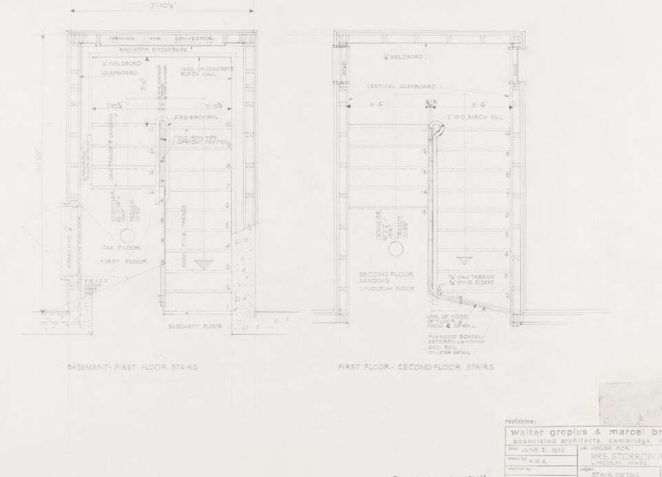
The image is a technical architectural drawing titled "Stair Detail Plans." The drawing includes detailed plans for stairs connecting the basement to the first floor and from the first floor to the second floor.
Key elements noted in the drawing:
Dimensions and Measurements:
- The width of the stair area is 7'-10 1/2".
Materials:
- Notations for materials such as welded board clapboard, concrete block wall, oak floor, linoleum floor, and birch rail.
Details for Stairs:
- Specifications for basement to first floor stairs include risers and treads details.
- Oak treads and pine risers are specified for stairs leading from the second floor landing.
Builders' Instructions:
- Notes remind contractors to verify all details and warn against scaling directly from the drawing.
Architects:
- The drawing is by Walter Gropius and Marcel Breuer, associated architects located in Cambridge, Mass.
Project Information:
- The drawing is for House for Mrs. Storrow (Ford), Lincoln, Mass.
- Date: June 21, 1939.
Additional Notes:
- Instructions for handrails, including a 2” birch rail.
- Radiator enclosure and convector openings are noted on the first floor.
- Vertical clapboard siding is to be used.
Revision Note:
- A small note indicating revisions and drawing office stamp in the lower right corner.
Overall, the drawing displays detailed floor plans for stairways within a specific residential project, outlining construction materials, measurements, and specific architectural elements for the project.
Created by gpt-4 on 2025-03-07
This image shows two detailed architectural drawings or blueprints of a staircase design. The drawings are laid out side by side, with annotations and measurements indicating precise dimensions, materials, and construction details. Labels identify the different floors (basement, first floor, and second floor) and parts of the staircase, such as the treads, risers, and railings. The plans include views for both basement-first floor stairs and first floor-second floor stairs.
There are also revision notations on the bottom right side, crediting "Walter Gropius & Marcel Breuer, architects, Cambridge, Mass." with additional notes pertaining to the project. These names suggest that the drawing is related to a project by two well-known architects who were influential in modern architecture. The presence of a stamp and signatures indicate that this is an official document that has undergone a review process.
The overall organization of the drawing conveys a professional and technical document, intended for use in the construction or renovation of a building where these staircase designs would be implemented.
Anthropic Claude
Created by us.anthropic.claude-3-5-sonnet-20241022-v2:0 on 2025-06-24
This image shows architectural stair detail plans from what appears to be a residential project. The drawing includes two stair sections:
- Basement-First Floor Stairs
- First Floor-Second Floor Stairs
The plans are quite detailed, showing various architectural elements including:
- Wallboard specifications
- Radiator enclosure details
- Concrete block wall specifications
- Vertical clapboard details
- Landing specifications
- Step dimensions and details
The drawing is from the architectural firm "Walter Gropius & Marcel Breuer Associates Architects, Cambridge" for what's labeled as the "Mrs. Storrow" project in Lincoln, Mass. It's labeled as drawing number 17 and specifically shows "Stair Detail Plans." The drawing includes technical specifications and measurements that would be used during construction.
The plans are drawn in a professional architectural style with clean lines and precise measurements, typical of mid-century modern architectural documentation.
Created by claude-3-haiku-20240307 on 2024-12-31
The image appears to be a detailed architectural blueprint or technical drawing of a set of stairs. It shows the layout and dimensions of the basement-first floor stairs as well as the first floor-second floor stairs. The drawing includes various measurements, labels, and notes related to the design and construction of these stairways. The overall style and presentation suggest this is an official technical document or plan, likely created by architects or engineers.
Created by claude-3-opus-20240229 on 2024-12-31
The image shows architectural floor plans for a basement and first floor level of a structure. The basement floor plan on the left has areas labeled as "Recreation Rm", "Elevator", "Vestibule", "Mechanical Rm", and "Toilet Rooms" among others. The first floor plan on the right includes a "Second Floor Landing", "Entrance Hall", "Corridor", "Kitchenette", and other spaces. The plans include dimensions and annotations indicating door swings, stairs, and other architectural details. A revision note in the bottom right references Walter Gropius & Marcel Breuer as the associated architects of the project, which appears to be a Star Detail Plans based on the title.
Created by claude-3-5-sonnet-20241022 on 2024-12-31
This is an architectural drawing showing stair details for a multi-level building. The drawing is divided into two main sections:
On the left: "BASEMENT-FIRST FLOOR STAIRS" showing the stairway details between the basement and first floor. It includes specifications for a radiator enclosure, wainscoting, and various measurements.
On the right: "FIRST FLOOR-SECOND FLOOR STAIRS" showing the stairway details between the first and second floors, including vertical clapboard and landing specifications.
The drawing is quite detailed, with precise measurements and notations throughout. It appears to be a professional architectural plan, as indicated by the title block at the bottom which shows it's drawing #17 and includes space for revisions. The drawing style is typical of architectural blueprints, using clean lines and standardized notation methods.
This appears to be for a residential project called "MRS. STORROW (FORD)" in Lincoln, Mass., designed by Walter Gropius & Marcel Breuer, Associated Architects, from Cambridge, Mass., dated June 21, 1939.
Meta Llama
Created by us.meta.llama3-2-11b-instruct-v1:0 on 2025-03-13
The image shows a technical drawing of the first and second floor stairs, with the title "BASEMENT-FIRST FLOOR STAIRS" and "FIRST FLOOR-SECOND FLOOR STAIRS" written below it. The drawing is divided into two sections, each showing a different floor plan.
First Floor Stairs:
- The first floor stairs are located on the left side of the drawing.
- The stairs consist of 17 steps, with a total rise of 7'10".
- The stairs have a landing at the top, which is 5'6" wide and 3'6" deep.
- The stairs are supported by a wall on the right side, which is 7'10" tall.
Second Floor Stairs:
- The second floor stairs are located on the right side of the drawing.
- The stairs consist of 15 steps, with a total rise of 7'10".
- The stairs have a landing at the top, which is 5'6" wide and 3'6" deep.
- The stairs are supported by a wall on the left side, which is 7'10" tall.
Additional Details:
- The drawing includes several notes and annotations, including measurements, labels, and symbols.
- The drawing is signed by two architects, Walter Gropius and Marcel Breuer, who are associated with the firm of Associated Architects.
- The drawing is dated June 21, 1935, and is labeled as "Revisions: Walter Gropius & Marcel Breuer."
Overall, the image provides a detailed and technical drawing of the first and second floor stairs, including their dimensions, layout, and supporting structures.
Created by us.meta.llama3-2-90b-instruct-v1:0 on 2025-03-13
The image depicts a technical drawing of the floor plan for a building, specifically focusing on the basement and first floor. The drawing is presented in black and white, with various details and labels indicating different features such as stairs, doors, and rooms.
Key Features:
- Floor Plan: The drawing shows the layout of the basement and first floor, including the location of stairs, doors, and rooms.
- Labels and Annotations: The drawing includes labels and annotations that provide additional information about the different features, such as the type of flooring, door sizes, and room dimensions.
- Scale: The drawing is drawn to scale, allowing for accurate measurements and calculations to be made.
- Architectural Style: The drawing suggests a modern or contemporary architectural style, with clean lines, minimal ornamentation, and an emphasis on functionality.
Overall Impression:
The image provides a detailed and informative view of the building's floor plan, highlighting the careful planning and attention to detail that has gone into its design. The use of labels and annotations adds an extra layer of clarity, making it easier to understand the different features and how they relate to each other.
Amazon Nova
Created by amazon.nova-lite-v1:0 on 2025-02-26
The image is a black-and-white architectural drawing of a residential house, specifically detailing the structural components and layout of the building. The drawing is labeled with various architectural terms and measurements. On the left side of the image, there is a vertical section of the building showing the basement, first floor, and second floor. The basement floor is indicated with a concrete foundation and a steel beam. The first floor shows a wooden staircase leading to the second floor. The second floor is detailed with a landing and a wooden floor. On the right side of the image, there is a horizontal section of the building showing the vertical cladding and the positioning of a birch rail. The drawing includes annotations such as "WELDED," "CONCRETE," "STEEL," and "WOOD," indicating the materials used in the construction. The drawing also includes the names of the architects, Walter Gropius and Marcel Breuer, and the date of the drawing, June 21, 1939. The drawing is labeled as "STAIR DETAIL," indicating that it is a detailed plan of the staircase in the house.
Created by amazon.nova-pro-v1:0 on 2025-02-26
The image is a blueprint of a building, specifically detailing the stairs between the basement and the first floor, as well as between the first and second floors. The blueprint is divided into two main sections, each depicting a different part of the building's vertical structure.
The left section of the blueprint shows the stairs leading from the basement to the first floor. It includes dimensions, such as the width of the stairs and the height of the risers, and notes about the construction materials and methods. The right section of the blueprint shows the stairs leading from the first floor to the second floor. This section also includes dimensions and construction details, as well as notes about the vertical clapboard and the location of the stairs in relation to other parts of the building.
Overall, the blueprint provides a detailed plan for the construction of the stairs in the building, including the materials, dimensions, and construction methods to be used.
Google Gemini
Created by gemini-2.0-flash on 2025-05-01
Here is a description of the image:
The image shows two architectural plans labeled "BASEMENT - FIRST FLOOR STAIRS" and "FIRST FLOOR - SECOND FLOOR STAIRS." Both plans depict staircase layouts with annotations indicating material types, dimensions, and design features.
The "BASEMENT - FIRST FLOOR STAIRS" plan includes details such as "WELDBORD," "CLAPBOARD," "FACE OF CONCRETE BLOCK WALL," "2.0D BIRCH RAIL," "OAK TREADS & LANDING," "HARD PINE TREADS," "OAK FLOOR," and "BASEMENT FLOOR." The dimensions are annotated throughout the plan, including the width of the opening ("7-10 ½") and the heights of the risers. There's also a note for a "CONVECTOR RADIATOR ENCLOSURE."
The "FIRST FLOOR - SECOND FLOOR STAIRS" plan includes "WELDBORD," "VERTICAL CLAPBOARD," "2.0D BIRCH RAIL," "OAK TREADS & PINE RISERS," "SECOND FLOOR LANDING LINOLEUM FLOOR," and a note for "PLYWOOD SCREEN BETWEEN LANDING AND RAIL TO LATER DETAIL." Dimensions and riser counts are annotated similarly to the first plan.
At the bottom right of the image, there's a section with revision information, listing "Walter Gropius & Marcel Breuer Associated Architects, Cambridge, Mass." The drawing is dated "JUNE 21, 1959," and it's for "MRS. STORROW (FORD) HOUSE, LINCOLN, MASS." The subject is "STAIR DETAIL PLANS," and the drawing is labeled as sheet number "17." A note at the bottom states, "The contractor must verify all dimensions on the job and report any discrepancies to the architects."
Created by gemini-2.0-flash-lite on 2025-05-01
This is a detailed architectural drawing of a staircase, likely for a residence. The drawing is labeled "Stair Detail Plans" and indicates the house was designed for Mrs. Storrow (Ford) in Lincoln, Massachusetts by architects Walter Gropius and Marcel Breuer.
Here's a breakdown of what's visible:
Elevation Views: The drawing provides two primary views, likely showing the stairs in cross-section.
- One view labeled "Basement - First Floor Stairs."
- The other view is labeled "First Floor - Second Floor Stairs."
Material and Construction Details: The plans specify materials and construction techniques, including:
- Oak flooring and treads.
- Hard pine treads.
- Birch rails.
- Concrete block wall.
- "Weldobord" components.
- Details on a "convector radiator enclosure."
- A "line of edge from or rail" and a "plywood screen between landing and rail."
Dimensions: The drawing is labeled with dimensions, allowing for accurate construction, including the overall width (7'-10 1/2").
Layers and Structure: The views show the staircase's structure, including the number of treads. There are also landings on both levels.
Annotations and Markings: There are notes and annotations indicating the location of various components, and references to different aspects.
Layout: The drawing shows a stairwell layout, with indications of how the stairs are placed within the building structure.
Date and Revisions: It has a date of June 21, 1939, with space for revisions. The drawing suggests an older style, with a focus on clarity and detail.
Overall, it's a professional architectural drawing focused on how the stairs were constructed.
Mistral Pixtral
Created by us.mistral.pixtral-large-2502-v1:0 on 2025-05-31
The image shows architectural drawings for a staircase design within a building. The drawings are detailed and include two sections: one for the basement to the first floor and another for the first floor to the second floor.
Left Section (Basement to First Floor Stairs):
- The drawing depicts the staircase from the basement to the first floor.
- Key elements include:
- Opening for Convector: Indicates space for a heating unit.
- Radiator Enclosure: Space designated for a radiator.
- Welded Clapboard: A type of siding material used.
- Wall of Concrete: Structural element of the building.
- Oak Birch Rail: Specifies the type of wood used for the railing.
- Oak Treads: Indicates the material for the steps.
- Oak Floor: The flooring material on the first floor.
- First Floor Landing: The area where the stairs end on the first floor.
- Basement Floor: The lower level where the stairs begin.
Right Section (First Floor to Second Floor Stairs):
- This drawing shows the staircase from the first floor to the second floor.
- Key elements include:
- Welded Clapboard: Similar siding material as in the basement section.
- Vertical Clapboard: Another type of siding material.
- Oak Birch Rail: The same type of railing as in the basement section.
- Second Floor Landing: The area where the stairs end on the second floor.
- Vinyl Floor: The flooring material on the second floor.
- Oak Treads: The material for the steps.
- First Floor: The lower level where the stairs begin.
- Plywood Soffit: A covering material used under the stairs.
- Second Floor Stairs: The staircase leading to the second floor.
Additional Information:
- The drawings are dated June 2, 1959, and are for a house for Mr. and Mrs. Harrow Ford in Lincoln, Massachusetts.
- The architects are Walter Gropius and Marcel Breuer, associated architects from Cambridge, Massachusetts.
- The drawings are part of a larger set of stair detail plans.
The detailed measurements and specifications provide a comprehensive guide for constructing the staircases, ensuring they meet the design and structural requirements.
Qwen
Created by Qwen/Qwen2.5-VL-72B-Instruct on 2025-07-21
This image is a detailed architectural drawing of stair detail plans for a house, designed by Walter Gropius & Marcel Breuer, Associated Architects, in Cambridge, Massachusetts. The drawing is dated June 21, 1939, and is for a house for Mrs. Storrow (Ford) in Lincoln, Massachusetts.
The drawing includes two sections:
Basement-First Floor Stairs: This section shows the construction details of the stairs leading from the basement to the first floor. It includes measurements and materials used, such as ¼" Weldbord clapboard, 2" O.D. birch rail, and ¾" oak treads. The drawing also indicates the presence of a radiation enclosure and a convocator opening.
First Floor-Second Floor Stairs: This section shows the construction details of the stairs leading from the first floor to the second floor. It includes similar measurements and materials, such as ¼" Weldbord, vertical clapboard, and 2" O.D. birch rail. The drawing also indicates the presence of a plywood screen between the landing and a later detail.
The drawing is detailed with various dimensions and notes, and it includes a scale of 3/4" = 1'-0". The revisions section at the bottom indicates that the contractor must verify all dimensions on the job and report any discrepancies to the architects. The drawing is numbered as 17.
Created by Qwen/Qwen2.5-VL-7B-Instruct on 2025-07-21
This image appears to be a set of architectural blueprints labeled "STAIR DETAIL PLANS," detailing the construction of stairs between the basement and the first floor, and the first floor and the second floor of a building. Both the left and right sides of the image show the same staircases with detailed dimensions for each component of the stairs, such as the tread depth, riser height, and the overall dimensions of the stairwell opening.
Key features include:
- Dimensions and Labels: The blueprint includes precise measurements and annotations for each part of the stairs, such as "2" O.D. BIRCH RAIL," "OAK TREADS," and "PINE RISERS." The dimensions are given in inches and fractions of inches.
- Material Specifications: The use of wood (oak treads, birch rails) and plywood is specified for the stair construction.
- Weldborod and Weldbord Clapboard: These are likely structural elements used in the construction of the stairwell.
- Radiation Enclosure: There is a note for an opening at the top of the stairwell for a convector, indicating a space for heating or cooling.
- Floor Levels: The blueprints indicate the positioning of the stairs between the basement, first floor, and second floor.
- Architectural Notes: At the bottom of the image, it is noted that the plans are for a house for Mrs. Storkow (Ford) in Lincoln, Massachusetts, designed by Walter Gropius & Marcel Breuer.
This type of blueprint is crucial for construction to ensure the stairs are built according to the architects' specifications.
Text analysis
Amazon