Machine Generated Data
Tags
Color Analysis
Feature analysis
Amazon
Clarifai

Clarifai
| Poster | 74.2% | |
Categories
Imagga
created on 2018-03-22
| text visuals | 100% | |
Captions
Microsoft
created by unknown on 2018-03-22
| a blackboard sign outside of a building | 57.2% | |
| a blackboard near a building | 57.1% | |
| a blue and white text | 57% | |
Clarifai
No captions written
Salesforce
Created by general-english-image-caption-blip on 2025-05-11
a photograph of a blueprinted drawing of a blueprinted plan of a house
Created by general-english-image-caption-blip-2 on 2025-06-28
blueprint of a building with plans and drawings
OpenAI GPT
Created by gpt-4 on 2024-12-16
This image is a blueprint. Blueprints are technical drawings that represent the design and specifications for constructing buildings or structures. The background of the image is a dark blue color with white lines and text, which is characteristic of traditional blueprints. This particular blueprint includes multiple views and details of a building, such as:
- The "First Floor Plan" showing the layout of rooms and spaces on the first floor.
- "Roof Plan" which outlines the structure and design details of the roof.
- "West Elevation", "East Elevation", and "South Elevation" which depict the exterior views of the building from the west, east, and south sides, respectively.
- Various detailed drawings and sections that provide a closer look at specific architectural and structural components, like window frames and wall sections.
The title block in the bottom right corner identifies the plan as the "Community Administration Building" and includes other information like the project number, sheet number, and possibly the firm or architect responsible for the design. The individual drawings include dimensions, labels, and notes, providing comprehensive technical details necessary for the construction process.
Created by gpt-4o-2024-05-13 on 2024-12-16
This image is a technical blueprint of a building, specifically named the "Community Administration Building" as indicated in the description at the bottom right corner. The blueprint has a deep blue background with white lines and text, typical of traditional architectural and engineering blueprints.
The blueprint includes several detailed views and plans:
- A first floor plan view showing the layout of various rooms and areas within the building.
- A roof plan indicating the top view of the building's roof structure.
- Elevation views (West, East, South, and North Elevations) displaying the exterior facade of the building from different angles.
- Detailed sections and construction details that provide specifics on building components such as wall sections, window framing, and other structural elements.
There are also annotations and measurements alongside each view and detail, specifying dimensions, materials, and other relevant construction information.
Overall, this blueprint serves as a comprehensive guide for the construction and architectural details of the Community Administration Building.
Anthropic Claude
Created by us.anthropic.claude-3-5-sonnet-20241022-v2:0 on 2025-06-24
This image appears to be an architectural blueprint or technical drawing with a dark blue background (commonly known as a "blueprint"). The drawing shows various architectural plans including:
- First Floor Plan
- Roof Plan
- Multiple Elevation Views (West, South, and North elevations)
The plans contain detailed measurements, room layouts, and architectural specifications drawn in white lines against the blue background. The drawing appears to be for some kind of administrative or institutional building, with various rooms and spaces clearly delineated. The plans include both structural elements and detailed annotations, which is typical of professional architectural drawings. The overall layout suggests this is a comprehensive building plan showing multiple views and specifications needed for construction.
The drawing has a professional, technical appearance with precise lines and measurements, and appears to be from an era when blueprints were actually blue (before modern printing methods took over).
Created by claude-3-haiku-20240307 on 2024-12-16
This image appears to be a blueprint or architectural drawing. It contains detailed technical diagrams and plans for a building or structure. The image shows various views, elevations, and floor plans, including the first floor plan, roof plan, east elevation, north elevation, and section details. The drawings are rendered in a traditional blueprint style, with white lines and text against a dark blue background. This type of detailed engineering drawing is commonly used in the design and construction of buildings, structures, and other architectural projects.
Created by claude-3-5-sonnet-20241022 on 2024-12-16
This is an architectural blueprint rendered in the classic blue and white cyanotype style. The drawing shows various views of what appears to be a community or administration building, including:
- First floor plan at the top
- Roof plan in the middle
- Multiple elevation views (West, East, South, and North) at the bottom
- Various architectural details and sections on the right side
The plans are highly detailed with precise measurements and annotations. The building appears to be a single-story structure with a linear layout. The elevation views show a modernist design with clean lines and what looks like large window sections. The document includes technical specifications and architectural details typical of professional construction drawings.
The blueprint's deep blue background contrasts sharply with the white lines of the drawings, which is characteristic of the traditional architectural blueprint reproduction process. In the bottom right corner, there appears to be a title block with project information, though the specific text is not clearly legible in this image.
Meta Llama
Created by us.meta.llama3-2-11b-instruct-v1:0 on 2024-12-16
The image presents a blue print of a building, featuring various architectural elements and measurements. The blue print is divided into sections, each detailing different aspects of the building's design.
- First Floor Plan
- The first floor plan is located at the top of the image and includes a layout of the rooms, corridors, and other features.
- It appears to be a residential or commercial building with multiple rooms, including a living room, kitchen, bedrooms, and bathrooms.
- The plan also shows the location of doors, windows, and other architectural elements.
- Roof Plan
- The roof plan is situated below the first floor plan and provides a detailed view of the building's roof structure.
- It includes information about the type of roofing material used, the pitch of the roof, and the location of vents, chimneys, and other roof features.
- West Elevation
- The west elevation is a side view of the building, showing its exterior appearance from the west.
- It includes details about the building's facade, including the type of materials used, the location of windows and doors, and any decorative elements.
- South Elevation
- The south elevation is another side view of the building, showing its exterior appearance from the south.
- It includes similar information to the west elevation, providing a comprehensive view of the building's design.
- North Elevation
- The north elevation is a side view of the building, showing its exterior appearance from the north.
- It includes details about the building's facade, including the type of materials used, the location of windows and doors, and any decorative elements.
- Section
- The section is a detailed view of a specific part of the building, such as a wall or a column.
- It provides information about the building's structural elements, including the type of materials used and the dimensions of the components.
- Elevation on South Wall at the Point of East Termination
- This section shows a detailed view of the south wall at the point where it meets the east wall.
- It includes information about the building's structural elements, including the type of materials used and the dimensions of the components.
- Community Administration Building
- This section provides information about the building's purpose and function.
- It includes details about the building's layout, including the location of offices, meeting rooms, and other facilities.
- Dimensions
- The dimensions section provides detailed measurements of the building's various components, including the length, width, and height of each room and feature.
- It also includes information about the building's footprint, including the size of the lot and the location of any adjacent buildings.
In summary, the image presents a comprehensive blue print of a building, featuring various architectural elements and measurements. The blue print is divided into sections, each detailing different aspects of the building's design, including the first floor plan, roof plan, west elevation, south elevation, north elevation, section, and elevation on south wall at the point of east termination. The dimensions section provides detailed measurements of the building's various components, including the length, width, and height of each room and feature. Overall, the image provides a thorough understanding of the building's design and layout.
Created by us.meta.llama3-2-90b-instruct-v1:0 on 2024-12-16
The image presents a blueprint for a building, featuring a dark blue background with white lines and text. The blueprint is divided into several sections, each displaying different views of the building's design.
Section 1: First Floor Plan
This section provides an overview of the building's first floor layout, including the location of rooms, corridors, and other features.
Section 2: Roof Plan
This section shows the roof's design, including the placement of vents, skylights, and other roof features.
Section 3: West Elevation
This section displays the building's west elevation, providing a detailed view of the exterior walls, windows, and doors.
Section 4: East Elevation
This section shows the building's east elevation, offering a similar view to the west elevation but from the opposite side.
Section 5: South Elevation
This section displays the building's south elevation, providing a detailed view of the exterior walls, windows, and doors.
Section 6: North Elevation
This section shows the building's north elevation, offering a similar view to the south elevation but from the opposite side.
Section 7: Community Administration Building
This section provides additional information about the building, including its name, address, and other relevant details.
Overall, the blueprint provides a comprehensive view of the building's design, allowing architects, engineers, and contractors to understand the project's requirements and specifications.
Amazon Nova
Created by amazon.nova-lite-v1:0 on 2025-02-24
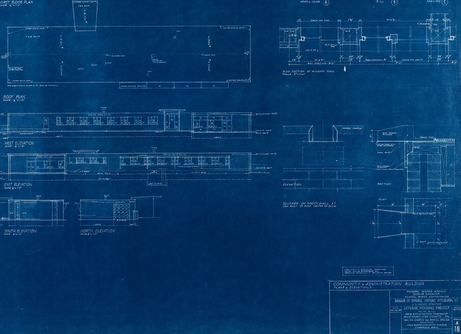
The image depicts a set of architectural blueprints for a building, specifically a "Community & Administration Building" designed by the Federal Works Agency. The blueprints are presented on a blue background, a common color for architectural plans, and include multiple sections detailing different aspects of the building's design. The blueprints feature floor plans, elevations, and sections, providing a comprehensive view of the building's structure.
The first floor plan is labeled and shows the layout of the building's interior spaces, including rooms and corridors. The roof plan is also included, illustrating the roof's structure and any relevant features. The west elevation shows the building's exterior from the west side, detailing the facade and any windows or doors. The east elevation provides a similar view from the east side.
Additionally, the blueprints include sections of the building, which are cross-sectional views that reveal the internal structure and materials used. These sections help in understanding the building's construction details, such as the placement of walls, floors, and ceilings.
At the bottom of the image, there is a detailed description of the project, including the name of the building, the agency responsible for the design, and the specific project details such as the location and the division of the Federal Works Agency responsible for the housing project.
Overall, the blueprints provide a thorough and technical overview of the building's design, intended for architects, engineers, and construction professionals to use in the planning and execution of the project.
Created by amazon.nova-pro-v1:0 on 2025-02-24
The image is a blueprint of a building with various sections and elevations. The blueprint is drawn on a blue background, with white lines and text. The top section of the blueprint shows the floor plan of the building, with different rooms and areas labeled. The bottom section of the blueprint shows the elevations of the building, with different elevations labeled for each side of the building. The blueprint also includes various notes and measurements, indicating the dimensions of the building and the materials used in its construction.
Google Gemini
Created by gemini-2.0-flash on 2025-05-13
Here's a description of the image:
The image is a blueprint for a "Community Administration Building." The blueprint includes several different views and detailed sections of the building.
The main components include:
- First Floor Plan: Shows the layout of the rooms on the first floor.
- Roof Plan: Shows the layout of the roof.
- Elevations: Includes West, East, South, and North Elevations, depicting the external views of the building from each direction.
- Detailed Sections: Shows detailed sections of the window frame, wall and scupper.
At the bottom right, there's a title block containing project information such as the project name, the Federal Works Agency, Division of Defense Housing, the location, and the architects.
Created by gemini-2.0-flash-lite on 2025-05-13
This image is a blueprint of a building. It appears to be a set of architectural plans, with different views and details. The blueprint is in the standard blue and white color scheme.
Here's a breakdown of what's visible:
- Plans: The image includes floor plans (first floor plan and a roof plan).
- Elevations: There are elevations of the building, indicating the exterior views.
- Sections: The blueprint also includes sections of the building, which means it shows internal views of how parts of the building are put together.
- Details: The plans showcase several details and dimensions.
- Title Block: The title block at the bottom-right provides information about the project, which is a Community Administration Building of Defense Housing in New Kensington Township.
Overall, it's a detailed architectural plan set, meant to guide the construction of the building.
Mistral Pixtral
Created by us.mistral.pixtral-large-2502-v1:0 on 2025-05-24
The image is a blueprint, which is a type of technical drawing used in architecture and engineering. This particular blueprint appears to be for a building, specifically labeled as a "Community & Administration Building" for the Federal Works Agency, Division of Defense Housing, in Phoenix, Arizona.
Here's a detailed summary of the various sections of the blueprint:
First Floor Plan:
- This section shows the layout of the first floor of the building. It includes various rooms and spaces, such as offices, corridors, restrooms, and possibly a reception area. The plan provides dimensions and spatial relationships between different parts of the floor.
Roof Plan:
- This section details the layout of the roof, including structural elements and possibly mechanical systems like HVAC units or roof access points.
West Elevation, East Elevation, South Elevation, and North Elevation:
- These sections show the external views of the building from the west, east, south, and north sides, respectively. They include details such as window placements, door locations, and the overall facade design.
Typical Jamb and Window Frame Sections:
- These are detailed cross-sectional views of window frames and jambs (the vertical sides of a window frame). They provide information on the construction and dimensions of these elements.
Section of Window Wall:
- This section shows a cross-sectional view of a window wall, detailing the structure and materials used in the wall that contains windows.
Sill, Head, and Jamb Details:
- These are detailed views of the sill (the bottom part of a window frame), head (the top part of a window frame), and jamb (the side parts of a window frame). They provide specific measurements and construction details.
Column on Foundation Detail:
- This section shows a detailed view of a column sitting on a foundation, including the structural elements and dimensions.
Typical Door Frame Section:
- This section provides a detailed view of a typical door frame, including dimensions and construction details.
Footing and Foundation Details:
- These sections show the details of the building's footing and foundation, including the structural elements and dimensions.
Overall, the blueprint provides a comprehensive set of drawings and details necessary for the construction of the Community & Administration Building, including floor plans, elevations, and detailed section views of various structural and architectural elements.
Qwen
Created by Qwen/Qwen2.5-VL-7B-Instruct on 2025-07-21
The image is a blueprint for a building, specifically for a "Community & Administration Building." The blueprint includes multiple technical drawings and specifications, providing details about the structure's design and construction. Key elements in the image include:
- First Floor Plan: This is the top-down view of the ground floor, detailing the layout of rooms, windows, and other features.
- Roof Plan: This shows the layout of the roof, including any vents, skylights, or other architectural elements.
- West Elevation, East Elevation, South Elevation, North Elevation: These are three-dimensional views of the building's exterior from the west, east, south, and north sides, illustrating the building's profile and window placement.
- Sections and Details: There are detailed drawings of various parts of the building, such as window frames, wall sections, and other architectural components, which are labeled and dimensioned.
- Window Frame Sections: These are close-up drawings of window frames, showing the thickness and details of the frame construction.
- Scale: The blueprint includes a scale indicating the size relationship between the drawing and the actual building (1/2" = 1'-0").
- Text and Notations: The blueprint contains text that provides additional information such as dimensions, materials, and specific construction instructions.
The blueprint appears to be a comprehensive guide for constructing the building, offering a clear and detailed plan for both the interior and exterior aspects.
Created by Qwen/Qwen2.5-VL-72B-Instruct on 2025-07-21
This image is a blueprint of a building, specifically labeled as a "Community & Administration Building." It appears to be an architectural drawing with detailed plans and elevations.
First Floor Plan: Located at the top left, it shows the layout of the first floor, including various rooms and spaces.
Roof Plan: Below the first floor plan, it provides the layout for the roof structure.
Elevations: On the left side, there are four elevations labeled as West, East, South, and North. These show the building's exterior views from different directions.
Sectional Views: On the right side, there are several detailed sectional views and cross-sections of different parts of the building, including windows, doors, and other structural elements.
Title Block: At the bottom right corner, there is a title block with information about the project. It includes the title "Community & Administration Building," the name of the agency responsible for the project (Federal Works Agency), the name of the firm responsible for the design (Dagron & Dean), the date (October 1943), and the location (Westmoreland County).
The blueprint is drawn on a blue background with white lines and text, which is typical for such architectural drawings. The scale and other technical details are also included to ensure accurate construction.
Text analysis
Amazon