Machine Generated Data
Tags
Color Analysis
Categories
Imagga
| text visuals | 47.3% | |
| nature landscape | 39.1% | |
| events parties | 8% | |
| beaches seaside | 3.9% | |
| sunrises sunsets | 0.7% | |
| cars vehicles | 0.5% | |
| streetview architecture | 0.2% | |
| food drinks | 0.1% | |
| paintings art | 0.1% | |
Captions
Microsoft
created on 2018-03-22
| a close up of a blue wall | 40.1% | |
| a close up of a blue background | 36.8% | |
| a blue ball | 13% | |
OpenAI GPT
Created by gpt-4 on 2024-12-16
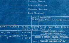
This is a blueprint-style image with white lines and text on a blue background, typical of architectural or engineering drawings. Such blueprints were historically made using a diazo print process, which produced white lines on a blue background. The image appears to be a technical drawing or plan of a road system with various symbols and notations. There are annotated lines representing what appear to be roads, paths, and boundaries. The structure of the lines indicates multiple different routes or links, with curves and intersections that suggest a network of streets or pathways. On the right side of the image, there is a legend titled "SYMBOLS," which likely explains the meaning of various lines and symbols used throughout the drawing. For example, "Pavement Edge," "Sewer Line," "Water Main," etc. At the bottom left corner, there's a "NOTE" section which is not clearly readable due to the resolution, but it seems to contain more detailed information about the contents or purpose of the drawing. The word "MATCH LINE" appears on the drawing itself, indicating a point where this plan would align with another plan sheet for continuity. Overall, the blueprint is a detailed technical document, most likely used for construction, urban planning, or civil engineering purposes.
Created by gpt-4o-2024-05-13 on 2024-12-16
This image is a blueprint drawing. Blueprints are technical drawings used to outline architectural or engineering designs. Key features of the blueprint include: 1. **Topographical Representation**: The drawing contains various topographical lines, indicating contours and elevations, which help in understanding the terrain. 2. **Infrastructure Layout**: It shows a layout plan with numerous straight and curved lines depicting roads or pathways. 3. **Detail Annotations**: There are annotations and labels indicating specific points or structures within the layout. 4. **Symbols Legend**: On the right side, there is a legend or key explaining the symbols used in the blueprint (e.g., property lines, sewer lines, water lines, etc.). 5. **Title Block**: The bottom right corner contains a title block providing further project details, such as the project name (Defense Housing Project), the plan type (Road Plans), dates, and drawing references. This type of document is typically used in civil engineering, land development, or architectural projects for planning and construction purposes.
Anthropic Claude
Created by claude-3-haiku-20240307 on 2024-12-16
This image appears to be a blueprint or engineering drawing of a road plan, showing the layout of roads, gas, sewer, and water lines. The image is in a distinctive blue color, which is characteristic of traditional blueprint designs. The drawing contains a variety of symbols and labels indicating different types of infrastructure, such as roads, pipelines, and other features. The overall impression is of a detailed technical diagram or plan for an urban or suburban development project.
Created by claude-3-5-sonnet-20241022 on 2024-12-16
This appears to be a vintage blueprint or technical drawing showing road plans, gas, sewer and water lines for what seems to be a housing development project. The image has the characteristic blue background with white lines typical of architectural blueprints. In the lower right corner, there's a title block with project information, and on the right side is a legend or "SYMBOLS" key explaining the various line types and markings used in the drawing. The main part of the drawing shows a network of interconnected lines representing different utility systems, with topographic contour lines suggesting the terrain's elevation changes. The drawing appears to be quite detailed and technical in nature, likely used for construction or engineering purposes.
Meta Llama
Created by us.meta.llama3-2-11b-instruct-v1:0 on 2024-12-16
The image presents a detailed blueprint or map of a large area, likely a military base or training facility. The map is rendered in white on a blue background and features various symbols and markings that provide information about the layout and features of the area. * **Map Features:** * The map appears to be a top-down view of a large area, possibly a military base or training facility. * It features various symbols and markings that provide information about the layout and features of the area. * The map includes roads, buildings, and other structures, as well as symbols for different types of land use, such as parking lots, gardens, and sports fields. * There are also symbols for different types of infrastructure, such as power lines, water pipes, and sewer systems. * The map includes a legend or key that explains the meaning of each symbol and marking. * **Symbols and Markings:** * The map uses a variety of symbols and markings to convey information about the area. * Some symbols are used to indicate the location of specific features, such as buildings, roads, and utilities. * Other symbols are used to show the boundaries of different areas or zones, such as parking lots, gardens, and sports fields. * The map also includes symbols for different types of land use, such as residential, commercial, and industrial areas. * The symbols and markings on the map are likely used by military personnel or other individuals who need to understand the layout and features of the area. * **Legend or Key:** * The map includes a legend or key that explains the meaning of each symbol and marking. * The legend is located in the bottom-right corner of the map and provides a clear and concise explanation of the symbols and markings used on the map. * The legend includes a list of symbols and their corresponding meanings, as well as a brief description of the area or feature represented by each symbol. * The legend is an important part of the map, as it allows users to quickly and easily understand the information presented on the map. Overall, the image presents a detailed and informative map of a large area, likely a military base or training facility. The map features various symbols and markings that provide information about the layout and features of the area, and includes a legend or key that explains the meaning of each symbol and marking.
Created by us.meta.llama3-2-90b-instruct-v1:0 on 2024-12-16
The image depicts a blue-tinted map with white lines and text, featuring various symbols and markings. The map appears to be a blueprint or technical drawing, possibly related to urban planning, architecture, or engineering. **Key Features:** * **Blue Tint:** The entire image has a blue tint, which is typical of blueprints or technical drawings. * **White Lines and Text:** White lines and text are used to represent various features on the map, such as roads, buildings, and symbols. * **Symbols and Markings:** The map includes various symbols and markings, which are likely used to convey specific information about the area being represented. * **Urban Planning or Architecture:** The map's content suggests that it may be related to urban planning, architecture, or engineering, given the presence of roads, buildings, and other infrastructure-related features. **Conclusion:** Based on the image's content and style, it is likely that the map is a technical drawing or blueprint used for urban planning, architecture, or engineering purposes. The blue tint and white lines and text are consistent with this interpretation, as are the various symbols and markings that are typical of technical drawings.
Amazon Nova
Created by amazon.nova-lite-v1:0 on 2025-02-26
The image is a blueprint or architectural plan printed on a blue background. The plan features a detailed layout of a property, with various lines and symbols indicating different features and structures. The plan includes contour lines, property lines, and sewer lines, among other details. The plan also includes a legend or key that explains the symbols used in the plan. The plan is labeled as "SYMBOLS" and includes a table with various symbols and their corresponding meanings.
Created by amazon.nova-pro-v1:0 on 2025-02-26
The image shows a blue-colored blueprint of a map with several lines and symbols. The map seems to be of a housing project. The map has a compass at the bottom right corner. There is a white box at the bottom right corner with the text "ROAD PLANS GAS, SEWER & WATER LINES" written on it. The map also has a white box with the text "SYMBOLS" written on it.
Text analysis
Amazon