Machine Generated Data
Tags
Color Analysis
Feature analysis
Amazon

| Document | 94.5% | |
Categories
Imagga
| text visuals | 100% | |
Captions
Microsoft
created by unknown on 2018-03-23
| a close up of text on a white background | 74.8% | |
| a close up of text on a black background | 69.4% | |
| a close up of text on a white surface | 69.3% | |
Clarifai
created by general-english-image-caption-blip on 2025-05-11
| a photograph of a drawing of a house with a lot of blueprints | -100% | |
Anthropic Claude
Created by claude-3-haiku-20240307 on 2024-12-31
This image appears to be an architectural blueprint or construction plan. It contains detailed diagrams, elevations, and floor plans for a multi-unit building or residential structure. The plans show the layout and dimensions of the various rooms, floors, and exterior features of the building. This type of technical drawing is commonly used by architects, engineers, and construction professionals to plan and document the design and construction of a built structure.
Created by claude-3-opus-20240229 on 2024-12-31
The image shows architectural plans and elevations for a building. It includes floor plans showing the layout of rooms, as well as front, rear and side elevation views depicting the exterior appearance of the structure from different angles. Various dimensions and technical details are annotated on the plans. Based on the title block in the bottom right, these appear to be plans and elevations for a "Titan Modular Project" by Inland Steel Company, though the specific type of building is not clear from the limited information provided. The plans are hand-drawn in a technical drafting style typical of architectural and engineering drawings.
Created by claude-3-5-sonnet-20241022 on 2024-12-31
This image shows an architectural drawing/blueprint that includes multiple views of what appears to be a residential building. The drawing contains several different components:
- A second floor plan
- A first floor plan
- A foundation plan
- Front elevation view
- Back elevation view
- End elevation view
- A section view
The drawings are technical in nature, showing detailed dimensions, room layouts, window and door placements, and other construction specifications. The style appears to be for what might be a duplex or multi-unit residential building, as there seems to be a symmetrical layout suggesting multiple living spaces. The drawings are done in the traditional architectural drafting style with clean lines and proper architectural notation and measurements.
The plans include both floor layouts and exterior elevations, giving a complete picture of how the building would look both inside and out. This appears to be a professional set of construction documents that would be used for building permits and construction purposes.
Amazon Nova
Created by amazon.nova-lite-v1:0 on 2025-05-28
This image is a technical architectural blueprint of a building. It includes various sections and views, such as floor plans, elevations, and a foundation plan. The blueprint is divided into different sections, each labeled with titles like "First Floor Plan," "Second Floor Plan," "Back Elevation," "Front Elevation," and "End Elevation." These sections provide detailed views of the building's layout, dimensions, and structural elements. The blueprint also includes notes and annotations, such as "Types B/C" and "Types A/C," which likely refer to different types of materials or construction methods used in the building. The image appears to be a high-quality, professionally printed blueprint, suitable for use in construction or architectural design.
Created by amazon.nova-pro-v1:0 on 2025-05-28
The image shows a floor plan of a building with several rooms and areas labeled. The plan is divided into different sections, including the first floor, second floor, and foundation plan. Each section has specific dimensions and annotations, indicating the layout and design of the building. The rooms are labeled with names such as "kitchen," "living," "bedroom," and "bathroom," providing insight into the intended use of each space. The image appears to be a detailed architectural plan, showcasing the structure and organization of the building.
Google Gemini
Created by gemini-2.0-flash on 2025-05-12
Here is a description of the image:
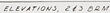
The image shows architectural plans and elevations for a 2ES ORM (or DRM) unit, likely a type of housing. The document includes various drawings with accompanying labels and scales.
The drawings show:
- Second Floor Plan: The layout of the second floor, labeled "Scale ¼ inch = 1 ft", indicates a building type of B & C. Bedrooms and a bathroom are visible.
- First Floor Plan: The layout of the first floor, also labeled "Scale ¼ inch = 1 ft" and building type B & C. Kitchen and living areas are marked.
- Foundation Plan: The layout of the foundation, labeled "Scale ¼ inch = 1 ft" and building type B & C, showing heater rooms and a crawl space.
- Back Elevation: A rear view of the building, labeled "Scale ¼ inch = 1 ft" and building type B & C, showing windows and doors.
- Front Elevation: A front view of the building, labeled "Scale ¼ inch = 1 ft" and building type B & C, showing windows.
- End Elevation: A side view of the building, labeled "Scale ¼ inch = 1 ft", with Type C - Type B similar.
- Section: A cut-through view, labeled "Scale ¼ inch = 1 ft", with Type C - Type B similar.
The title of the document is "Plans & Elevations, 2ES ORM Unit" along with the information that this plan originates from the Division of Defense Housing in Pittsburgh and it is a defense housing project.
Created by gemini-2.0-flash-lite on 2025-05-12
The image is a blueprint or architectural drawing. It contains multiple views of a building, including floor plans (first and second floors), elevation views (front, back, and end), and a section view. The drawing includes dimensions and labels, indicating the layout of rooms, windows, doors, and other architectural details. The title block suggests this is a design for a "2ES DRM Unit" for the Defense Housing Project, including information about the design process and the architects involved. The scale is provided for each view.
Text analysis
Amazon