Machine Generated Data
Tags
Color Analysis
Categories
Imagga
| text visuals | 99.9% | |
Captions
Microsoft
created on 2018-03-22
| a blue and white text | 82.2% | |
| a blackboard near a building | 79.9% | |
| a blackboard near a blue wall | 75.5% | |
OpenAI GPT
Created by gpt-4 on 2024-12-16
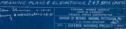
This image displays a set of blueprints, created using the traditional blueprint process that yields white lines on a blue background. The blueprints contain architectural drawings that include a variety of floor plans, elevations, and sections of a building. Different parts of the drawing are labeled, such as "second floor framing plan," "back elevation framing," "front elevation framing," and more. There are numerous annotations and dimensions provided, specifying the details needed for constructing the represented structure. These blueprint drawings are useful for constructors, architects, and engineers to understand all aspects of the building design.
Created by gpt-4o-2024-05-13 on 2024-12-16
The image depicts a detailed architectural blueprint. Blueprints are technical drawings used in architecture and engineering, typically printed on blue paper with white lines. The blueprint presents various sections and elevations for a building, including detailed framing plans. Here are some specific elements visible on the blueprint: - **Roof Framing Plan**: This section details the layout and structure of the roof, noting specific dimensions and positions for framing materials. - **Second Floor Framing**: Shows the layout for framing the second floor, with measurements and notes concerning the placement of structural elements. - **First Floor Framing**: Similar to the second floor, this section details the framing plan for the first floor. - **Back Elevation Framing**: Provides a view of the back elevation, showing how the framing will look from behind. - **Front Elevation Framing**: Offers details on the front view of the building's framing structure. - **Framing Sections & Elevations**: This part includes various smaller views, sections, and elevation details to aid in the construction process. In the lower right corner, there is a title block with information about the project, possibly indicating the project name, date, and other administrative details. The blueprint appears to be titled "Framing Plans & Elevations" and shows detailed drawings for "2-3 Bdrm Units" under the “Defense Housing Project” label. This indicates it may be part of a larger construction project for housing units.
Anthropic Claude
Created by claude-3-haiku-20240307 on 2024-12-16
This image appears to be a blueprint or architectural drawing, likely for a building or structure. The blueprint contains detailed technical drawings, measurements, and annotations in a distinctive blue-and-white color scheme characteristic of traditional blueprint designs. The drawings depict various elevations, floor plans, and structural details of the building, indicating this is a comprehensive set of construction plans. Overall, this image provides a detailed technical overview of the architectural design for a structure or facility.
Created by claude-3-5-sonnet-20241022 on 2024-12-16
This image shows a detailed architectural blueprint with a classic blue background, typical of traditional blueprints. It appears to be a complete set of framing plans and elevations for what seems to be a residential or small commercial building. The plans include multiple views: floor framing plans for both first and second floors, back elevation framing, and various other structural details. The drawings feature precise measurements, structural notations, and detailed framing specifications. In the bottom right corner, there's a title block that appears to contain project information and specifications. The overall layout is well-organized with different sections clearly separated and labeled. The white lines and text stand out crispy against the deep blue background, making this a classic example of architectural documentation from before the era of digital drafting.
Meta Llama
Created by us.meta.llama3-2-11b-instruct-v1:0 on 2024-12-16
The image presents a detailed blueprint for a building, featuring a blue background with white lines and text. The blueprint is divided into sections, each containing various architectural elements such as walls, windows, doors, and staircases. **Key Features:** * **Background:** The blueprint has a blue background with white lines and text. * **Divisions:** The blueprint is divided into sections, each containing various architectural elements. * **Elements:** The sections include walls, windows, doors, and staircases. * **Text:** The blueprint includes text that provides additional information about the building's design and specifications. **Purpose:** The purpose of this blueprint is to provide a detailed and accurate representation of the building's design and layout. It is likely used by architects, engineers, and contractors to ensure that the building is constructed according to the original plans and specifications. **Conclusion:** In conclusion, the image presents a detailed blueprint for a building, showcasing its various architectural elements and providing a comprehensive overview of the building's design and layout. The blueprint is an essential tool for architects, engineers, and contractors to ensure that the building is constructed accurately and efficiently.
Created by us.meta.llama3-2-90b-instruct-v1:0 on 2024-12-16
The image presents a comprehensive set of architectural drawings, likely for a building or structure, showcasing various elevations and floor plans. The drawings are rendered in white on a blue background, with each section labeled to facilitate easy navigation. **Key Features:** * **Elevations:** The image includes multiple elevation views, which provide a detailed representation of the building's exterior from different angles. These views help visualize the structure's design and layout. * **Floor Plans:** In addition to elevations, the image features floor plans that outline the interior layout of the building. These plans typically include room dimensions, door and window locations, and other essential details. * **Labels and Annotations:** Throughout the drawings, labels and annotations are used to identify specific features, such as rooms, doors, windows, and other architectural elements. These labels enhance the clarity and understanding of the design. * **Scale and Measurements:** The drawings likely include a scale or measurement system to ensure accurate interpretation and implementation of the design. **Purpose and Context:** * **Architectural Design:** The primary purpose of these drawings is to communicate the architectural design and layout of the building to stakeholders, including architects, engineers, contractors, and clients. * **Construction Planning:** The drawings serve as a crucial tool for construction planning, enabling teams to prepare for the building process by identifying materials, labor requirements, and potential challenges. * **Compliance and Regulation:** The drawings may also be used to demonstrate compliance with local building codes, zoning regulations, and other relevant standards. In summary, the image provides a detailed and informative visual representation of a building's design, facilitating effective communication among stakeholders and supporting the construction process.
Amazon Nova
Created by amazon.nova-pro-v1:0 on 2025-02-27
The image is a blueprint of a building, specifically detailing the framing plans and elevations for the second and third floors. The blueprint is drawn on a blue background, a common practice in architectural drawings to enhance visibility and contrast. The blueprint includes several sections: 1. **Framing Plans**: - **Second Floor Framing**: This section shows the layout of the structural framing for the second floor. It includes beams, joists, and supports, indicating how the floor is constructed to bear loads. - **Third Floor Framing**: Similar to the second floor, this section details the framing for the third floor, showing the arrangement of beams and joists. 2. **Elevations**: - **Front Elevation Framing**: This part of the blueprint provides a side view of the building's front, showing the arrangement of walls, windows, and other architectural features. - **Back Elevation Framing**: This section shows the rear view of the building, detailing the same elements as the front elevation but from the opposite side. 3. **Details**: - **Rear Elevation Details**: This section offers a more detailed look at specific parts of the rear elevation, possibly highlighting unique features or construction techniques. 4. **General Information**: - The blueprint includes labels and notes such as "Framing Plans & Elevations 2 & 3 Floors," "Second Floor Framing," "First Floor Framing," and "Front Elevation Framing." These labels help identify each section of the blueprint. 5. **Additional Notes**: - There are additional notes and measurements provided throughout the blueprint, which are essential for construction workers and engineers to understand the specific requirements and dimensions of the building. 6. **Project Information**: - At the bottom right corner, there is a section with project details, including the project name ("Defense Housing Project"), location, and other relevant information. This section also includes the date, client information, and possibly the architect's or engineer's signature. **Analysis**: The blueprint is a comprehensive guide for the construction of the second and third floors of a building. It provides detailed information on the structural framing and elevations, ensuring that all construction elements are accurately implemented. The use of a blue background enhances the readability of the white lines and text, making it easier for construction professionals to interpret the plans. The inclusion of specific details and project information ensures that all stakeholders have the necessary data to proceed with the construction process effectively.
Created by amazon.nova-lite-v1:0 on 2025-02-27
The image is a blue architectural blueprint featuring various sections of a building's framing plans. The blueprint is divided into several sections, each labeled with different parts of the building, such as "ROOF FRAMING PLAN," "SECOND FLOOR FRAMING," and "FRONT ELEVATION FRAMING." Each section includes detailed drawings and measurements, with lines and text indicating dimensions, materials, and structural components. The blueprint also includes notes and annotations in the lower right corner, providing additional information about the project, such as the name of the architect, the date, and the scale of the drawings.
Text analysis
Amazon