Machine Generated Data
Tags
Color Analysis
Feature analysis
Amazon
Clarifai

Clarifai
| Poster | 96.7% | |
Categories
Imagga
created on 2022-05-28
| text visuals | 98.6% | |
Captions
Microsoft
created by unknown on 2022-05-28
| diagram, engineering drawing | 99.7% | |
Clarifai
No captions written
Salesforce
Created by general-english-image-caption-blip on 2025-05-13
a photograph of a diagram of a satellite satellite satellite system
Created by general-english-image-caption-blip-2 on 2025-06-30
a blueprint of a building with a diagram of the different parts
OpenAI GPT
Created by gpt-4 on 2024-12-05
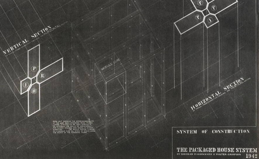
This image is a reproduction of an architectural drawing in white on a dark background, likely a negative of the original drawing. It is titled "THE PACKAGED HOUSE SYSTEM" by Konrad Wachsmann and Walter Gropius, dated 1942. The drawing explains a construction system with two main diagrams labeled "VERTICAL SECTION" on the left and "HORIZONTAL SECTION" on the right, accompanied by an isometric illustration of the house structure in the center.
The "VERTICAL SECTION" diagram appears to illustrate the intersection of different structural components at a joint, labeled P (panel), R (rails), and H (the hollow section at the joint). The "HORIZONTAL SECTION" seems to mirror this concept but for a horizontal perspective with corresponding systems intersecting.
Below the "VERTICAL SECTION," there is text that is not entirely clear due to the resolution, but it mentions something about the interchangeability, the system's basic and secondary elements, the erection sequence, and the width of standardized panels.
The central part of the drawing shows the overall modular construction system with grid lines that imply prefabricated units or modules making up the structure, labeled "MODULE" and "CUBE."
This image demonstrates the concept of prefabricated housing, focusing on modularity and ease of assembly, which was a research and design interest of architects during that period. Walter Gropius was a well-known architect associated with the Bauhaus movement, which emphasized modernist design and advances in building technologies.
Created by gpt-4o-2024-05-13 on 2024-12-05
This image is a black and white architectural diagram titled "SYSTEM OF CONSTRUCTION" from the "PACKAGED HOUSE SYSTEM" by Konrad Wachsmann and Walter Gropius, dated 1942.
The diagram presents a detailed isometric view of a modular construction system. It features a "MODULE CUBE" structure at the center, with two detailed sectional views to the left and right:
- Vertical Section: This section shows the design from a vertical perspective with components labeled (P, R, H, I).
- Horizontal Section: This section provides a horizontal perspective with components labeled (V, P, E).
Additionally, there is explanatory text in the diagram that describes the interchangeability and modularity of these construction units. The text mentions that the room units can be assembled at the factory and then combined on site in various configurations to form a standard framework. The drawing includes precise alignment and connection details between different modules, illustrating how the system works from both vertical and horizontal aspects.
Anthropic Claude
Created by claude-3-haiku-20240307 on 2024-12-05
This image appears to be an architectural plan or technical drawing for a "packaged house system" of construction, showing various cross-sections and views. The drawing includes labels such as "Vertical Section" and "Horizontal Section" indicating different perspectives of the structural design. The overall impression is of a detailed, technical illustration that likely served as a blueprint or schematic for the construction of this particular prefabricated or modular housing system.
Created by claude-3-5-sonnet-20241022 on 2024-12-05
This is an architectural blueprint or technical drawing from 1942 titled "The Packaged House System" by Konrad Wachsmann & Walter Gropius. The drawing shows a "System of Construction" with both vertical and horizontal sections detailed. The image features isometric diagrams showing how different modular components fit together, with letters (P, I, R, H) marking different parts of the joint system. There's a central perspective drawing showing what appears to be a modular cube or frame structure. The drawing is rendered in white lines on a dark background, typical of architectural blueprints of that era. This appears to be part of a larger documentation for a modular housing construction system, showing innovative joining methods and structural details.
Created by us.anthropic.claude-3-5-sonnet-20241022-v2:0 on 2025-06-26
This is an architectural blueprint or technical drawing from 1942 titled "The Packaged House System" by Konrad Wachsmann and Walter Gropius. The drawing shows a construction system detail, featuring both vertical and horizontal sections of what appears to be a modular building component. The image includes cross-sectional diagrams showing how different parts (labeled with letters P, I, R, H) connect together in an X-shaped joint configuration. There's also a three-dimensional wireframe or perspective drawing in the middle showing how these components would fit together in the actual structure. The drawing is presented in white lines on a dark background, typical of architectural blueprints of that era. This appears to be part of a larger documentation for a prefabricated housing system, which was an innovative approach to construction at the time.
Meta Llama
Created by us.meta.llama3-2-11b-instruct-v1:0 on 2024-12-05
The image depicts a technical drawing of a modular house system, showcasing the design and construction details of the structure. The drawing is presented on a black background with white lines and text, providing a clear visual representation of the system's components and layout.
Key Features:
- Modular Design: The drawing illustrates a modular house system, comprising interconnected modules that can be assembled to form a larger structure.
- Components: The system includes various components, such as walls, floors, and roofs, which are labeled and detailed in the drawing.
- Assembly: The drawing provides instructions on how to assemble the modules, including the placement of walls, floors, and roofs.
- Dimensions: The drawing includes measurements and dimensions for each component, ensuring accurate assembly and construction.
- Text: The drawing includes text that provides additional information about the system, such as its name, "THE PACKAGED HOUSE SYSTEM," and the authors, "BY RONALD WAGENMANN & WALTER GROPHUS."
Overall:
The image presents a detailed and technical drawing of a modular house system, providing a comprehensive overview of its design and construction. The drawing is well-organized and easy to follow, making it a valuable resource for architects, builders, and anyone interested in modular construction.
Created by us.meta.llama3-2-90b-instruct-v1:0 on 2024-12-05
The image is a technical drawing of a house, titled "THE PACKAGED HOUSE SYSTEM" and dated 1942. The drawing is in black and white, with white lines on a black background.
Title and Date
- The title is written in large white letters at the bottom right corner of the image.
- The date "1942" is written below the title.
Drawing
- The drawing shows a house with a rectangular shape and a pitched roof.
- The house has several windows and doors, which are represented by small rectangles and squares.
- The drawing also includes various details such as roof beams, walls, and a foundation.
- There are several sections of the house that are labeled, including a "VERTICAL SECTION" and a "HORIZONTAL SECTION".
- These sections show the internal structure of the house, including the placement of walls, floors, and ceilings.
Labels and Annotations
- Throughout the drawing, there are various labels and annotations that provide additional information about the house.
- These labels include measurements, materials, and construction details.
- Some of the labels are written in small text, while others are larger and more prominent.
Overall
- The image appears to be a detailed technical drawing of a house, created for architectural or engineering purposes.
- The drawing provides a comprehensive view of the house's design and construction, including its layout, materials, and structural elements.
Amazon Nova
Created by amazon.nova-lite-v1:0 on 2025-02-26
The image is a technical drawing of a house construction system, titled "The Packaged House System" by Konrad Wachsmann and Walter Gropius, dated 1942. The drawing is on a black background and contains several labeled components. The central focus is a cross-sectional view of a house module, showing the interchangeability of various elements. The labels include "P" for panel, "R" for roof, "I" for interior, and "H" for horizontal. There are also annotations explaining the system's design, such as "Typical Frame Connection" and "Typical Frame Connection (Squiring)." The drawing provides a detailed look at how different parts of the house can be assembled and connected.
Created by amazon.nova-pro-v1:0 on 2025-02-26
The image is a technical drawing of a construction system, specifically "The Packaged House System" by Konrad Wachsmann and Walter Gropius, dated 1942. The drawing is in black and white and includes several sections and annotations. The top right corner of the image is labeled "1". The drawing consists of a vertical section and a horizontal section of a modular cube structure. The vertical section shows a series of interconnected modules, with labels "P" and "R" indicating different components. The horizontal section shows the arrangement of these modules in a grid-like pattern, with labels "P" and "I" indicating different components. The drawing also includes annotations and measurements, such as "MODULE CUBE" and "INTERCHANGEABILITY OF THE BASIC STANDARD PANEL FRAME." The drawing is a technical representation of a construction system that aims to standardize and simplify the building process.
Google Gemini
Created by gemini-2.0-flash on 2025-04-27
Here is a description of the image:
The image is a technical architectural drawing from 1942 titled "The Packaged House System" by Konrad Wachsmann & Walter Gropius, focusing on a system of construction. The drawing is done in white lines on a dark background, reminiscent of blueprints.
On the left side of the image, there is a "VERTICAL SECTION" of a typical frame connection that is equal to the horizontal section, featuring a close-up of the joint where frame members intersect. Inside the joint are letters: "P", "R", "I", and "H".
In the center, there is a three-dimensional, wireframe representation of a modular cube, labeled "MODULE CUBE." This cube is likely the basic unit for the proposed construction system.
On the right side, there is a "HORIZONTAL SECTION" detail. The upper right of the image features a large number "1."
Below the modular cube, the title "SYSTEM OF CONSTRUCTION" is printed, followed by the project title and authors.
In the bottom left, there is a description of the room unit, emphasizing the interchangeability of the frame panels for walls, floors, ceilings, and roofs in either direction. The whole system is based on a module cube, all sides of which equal the width of the standard frame.
Created by gemini-2.0-flash-lite on 2025-04-27
The image is a blueprint or architectural diagram of "The Packaged House System" designed by Konrad Wachsmann and Walter Gropius in 1942. It's a technical drawing with a dark background and white lines, typical of blueprints.
Key components and features of the image include:
- Title: The title "The Packaged House System" is prominently displayed, along with the names of the designers and the year, 1942.
- Sections and details: The image displays both vertical and horizontal sections, showcasing the structural frame. The connections between parts are shown, marked with letters "P", "R", "I", and "H".
- Module Cube: The design highlights the concept of a "module cube," which appears to be the basic building block of the house. The cube's frame is outlined.
- Construction System: The overall "System of Construction" suggests a prefabricated or modular approach to building, allowing for easy assembly.
- Text and Annotations: The blueprint contains explanatory text with details about the room unit showing the interchangeability of the parts, emphasizing a design focused on standardized components.
- Perspective View: The drawing uses perspective to give a three-dimensional view of the house's structure, aiding in visualizing the design.
- Overall Aesthetic: The image has a vintage look because of the black background and the white lines, typical of the architectural drawings of the time.
Mistral Pixtral
Created by us.mistral.pixtral-large-2502-v1:0 on 2025-04-27
This image is an architectural drawing titled "The Packaged House System" by Konrad Wachsmann and Walter Gropius, dated 1942. It illustrates a system of construction for a modular house.
The drawing is divided into three main sections:
Vertical Section:
- This section shows a vertical cross-section of the house, illustrating how different modules are stacked vertically. The labeled parts include:
- P: Possibly denoting a public space or a particular module.
- R: Likely indicating a residential or private module.
- H: Could stand for a horizontal or another specific module.
- I: Might represent an intermediary or connecting module.
- This section shows a vertical cross-section of the house, illustrating how different modules are stacked vertically. The labeled parts include:
Module Cube:
- The central part of the drawing displays a three-dimensional representation of the modular cube. This cube is the basic unit of the packaged house system, showing how the different parts fit together in a three-dimensional space.
Horizontal Section:
- This section shows a horizontal cross-section of the house, illustrating the layout of the modules when viewed from above. The labeled parts include:
- P: Again, likely denoting a public or specific module.
- R: Indicating a residential or private module.
- V: Could stand for vertical or another specific module.
- I: Representing an intermediary or connecting module.
- This section shows a horizontal cross-section of the house, illustrating the layout of the modules when viewed from above. The labeled parts include:
The drawing emphasizes the modularity and flexibility of the construction system, showing how standardized units can be combined in different configurations to create a variety of living spaces. The text at the bottom right corner confirms the title and the authors of the system.
Qwen
Created by Qwen/Qwen2.5-VL-7B-Instruct on 2025-06-29
The image is a technical drawing or blueprint that illustrates a "System of Construction" for "The Packaged House System." The drawing is in black and white, with a dark background and white lines creating a detailed, three-dimensional perspective. It includes a vertical and a horizontal section of the house system, labeled accordingly.
Key elements of the drawing include:
- Vertical Section: A diagram on the left side of the image that appears to show the vertical arrangement of the house's structural components.
- Horizontal Section: A diagram on the right side of the image that shows the horizontal layout of the house's structure.
- Module Cube: A central large cube structure, which is likely a part of the house's modular design.
- Interchangeability: The text at the bottom suggests that the design emphasizes the interchangeability of the base standard main frames, allowing for flexibility in how the house can be assembled or disassembled laterally for walls or horizontally for floors.
- Authors and Year: The drawing is credited to "Konrad Wachsmann & Walter Gropius" and dated 1942.
The overall design is geometric and modular, suggesting a futuristic or innovative approach to housing construction, possibly for prefabrication or industrialized building methods.
Created by Qwen/Qwen2.5-VL-72B-Instruct on 2025-06-29
The image is a technical architectural drawing showing the "System of Construction: The Packaged House System" by Konrad Wachsmann and Walter Gropius, dated 1942. The drawing is presented on a dark gray background with white lines and text, giving it a high-contrast appearance.
The central feature of the drawing is a three-dimensional isometric view of a modular house structure. This structure is composed of several cube-shaped modules, which are connected to form a larger building. The modules are labeled "MODULE CUBE," indicating the basic building blocks of the system.
On either side of the central structure, there are detailed sectional drawings. On the left side, there is a "VERTICAL SECTION," showing a cross-sectional view of the house from a vertical perspective. On the right side, there is a "HORIZONTAL SECTION," showing a cross-sectional view from a horizontal perspective. Both sections highlight the internal layout and structural details of the house.
The sections also include a diagram of a module with various letters (P, R, H, etc.) labeled, possibly indicating different functional areas or components within the module. The diagram on the right side includes additional annotations and symbols, further detailing the construction system.
At the bottom of the image, there is a caption that reads "SYSTEM OF CONSTRUCTION THE PACKAGED HOUSE SYSTEM BY KONRAD WACHSMANN & WALTER GROPIUS 1942," providing the title and the creators of the design.
Overall, the image is a detailed technical drawing that illustrates a modular construction system for houses, emphasizing the use of standardized components and their assembly into a larger structure.
Text analysis
Amazon