Machine Generated Data
Tags
Color Analysis
Categories
Imagga
| text visuals | 99.8% | |
| paintings art | 0.2% | |
Captions
Microsoft
created on 2018-03-22
| a close up of text on a whiteboard | 69.6% | |
| close up of text on a whiteboard | 66.8% | |
| a close up of a whiteboard | 65.4% | |
OpenAI GPT
Created by gpt-4 on 2025-03-09
The image displays an architectural drawing that includes both plans and elevations. On the left side of the sheet, there is a drawing labeled "West Wall Elevation" and another labeled "North West Corner," with specific measurements and construction details, such as "cement wash," "rubber roofing," and other technical notes.
The larger drawing on the right shows a "Roof Framing Plan," with a grid pattern representing beams, which are annotated with dimensions and notes like "existing joists," "steel tube column," and directional orientations (like "North").
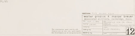
The sheet includes a title block in the bottom right corner, which contains information pertaining to the project. This includes the project name "Water Group 4" and the architect "Marcel Breuer and Associates, Architects." It provides the address in Cambridge, Massachusetts, a drawing number (which appears to be 12), the date of the drawing, and notes regarding revisions.
This architectural drawing is likely intended for professional use during the construction or renovation process of a building, and it details the specific architectural elements designed by the architects mentioned.
Created by gpt-4o-2024-05-13 on 2025-03-09
The image depicts a technical architectural drawing for a roof framing plan with additional detailed sections. This plan is labeled "ROOF FRAMING PLAN" with a scale of 1/4" = 1' - 0". The main roof plan covers the central portion of the image, showing the layout and arrangement of the roof's framing components, including beams and other structural elements.
Below the main roof plan are two detailed views labeled "VENT HOLE IN NORTH E BEAM LINE ELEVATION - FULL SIZE - SECTION". These provide an enlarged and detailed depiction of specific components related to a vent hole in the north elevation, including dimensions and construction details.
The drawing includes a title block at the bottom right corner. The title block contains the following information:
- Project: GROSSMAN HOUSE
- Associated Architects: WALTER GROPIUS & MARCEL BREUER
- Location: CAMBRIDGE, MASS
- Scale: 1/4" = 1' - 0"
- Drawing Number: 12
- Revisions noted with a date of 10 APR. 1935
This technical document would be used by builders and contractors to construct the roof structure according to the architect's specifications.
Anthropic Claude
Created by claude-3-haiku-20240307 on 2024-12-31
This image appears to be an architectural or engineering drawing, specifically a roof framing plan. It contains various dimensions, measurements, and technical annotations that suggest it is a construction or design document. The main part of the image shows a grid-like layout with labeled sections, likely representing the structural framework of a roof. Additional smaller drawings on the sides provide further details or views of the planned construction. Overall, this appears to be a technical drawing used in the planning and design process for a building or structure.
Created by claude-3-opus-20240229 on 2024-12-31
The image shows architectural plans or blueprints drawn on a light background. The plans depict the layout and dimensions of what appears to be a rectangular structure, likely a building or house. Measurements and annotations are included on the plans to specify sizes and details of the various rooms and spaces. The plans are neatly drawn with thin lines in a technical drafting style. Some text is visible at the bottom providing a description or title for the plans, but the full details are cut off in this cropped view of the document.
Created by claude-3-5-sonnet-20241022 on 2024-12-31
This appears to be an architectural drawing or blueprint. It shows various technical details including what appears to be a roof framing plan and elevation drawings. The document has a title block in the bottom right corner indicating it was created by Walter Gropius & Marcel Breuer architectural firm. The drawing is quite sparse and minimal, with thin lined drawings against a white background. There are grid patterns and measurement markings visible in different sections of the plan. The overall style is consistent with mid-century modern architectural documentation.
Meta Llama
Created by us.meta.llama3-2-11b-instruct-v1:0 on 2025-03-16
The image is a technical drawing of a building's roof framing plan, featuring a detailed blueprint with various lines and labels. The drawing appears to be hand-drawn on white paper with black ink.
Key Features:
- Blueprint: The drawing is a technical blueprint, likely created for construction or architectural purposes.
- Hand-Drawn: The drawing is hand-drawn, indicating a personal touch or a more traditional approach to creating technical drawings.
- White Paper: The drawing is made on white paper, which provides a clean and neutral background for the technical details.
- Black Ink: The drawing is created with black ink, which provides good contrast and visibility for the technical details.
- Lines and Labels: The drawing features various lines and labels, which are used to convey technical information about the building's roof framing plan.
Purpose:
The purpose of the drawing is to provide a detailed and accurate representation of the building's roof framing plan, which is essential for construction or architectural purposes. The drawing is likely used to communicate technical information to architects, engineers, or contractors who need to understand the building's design and layout.
Conclusion:
In conclusion, the image is a technical drawing of a building's roof framing plan, created using hand-drawn techniques on white paper with black ink. The drawing features various lines and labels that convey technical information about the building's design and layout. The purpose of the drawing is to provide a detailed and accurate representation of the building's roof framing plan, which is essential for construction or architectural purposes.
Created by us.meta.llama3-2-90b-instruct-v1:0 on 2025-03-16
The image presents a technical drawing of a building's roof framing plan, showcasing the architectural design and structural elements. The drawing is rendered in black ink on white paper, with a focus on precision and detail.
Key Features:
- Roof Framing Plan: The central element of the drawing, depicting the roof's structure and layout.
- Sectional Views: Two smaller drawings on the left side provide sectional views of the building, offering additional context and detail.
- Labeling and Notations: The drawing includes various labels and notations, likely indicating materials, dimensions, and other relevant information.
- Scale and Measurements: A scale is provided in the bottom-right corner, allowing for accurate measurement and interpretation of the drawing.
- Architectural Firm Information: The bottom-right corner also features the name and contact information of the architectural firm responsible for the design, along with a project number and date.
Overall Impression:
The image conveys a sense of professionalism and attention to detail, suggesting that the architectural firm has carefully considered the building's design and structural integrity. The inclusion of sectional views and labeling adds depth and complexity to the drawing, making it a valuable resource for architects, engineers, and builders.
Amazon Nova
Created by amazon.nova-lite-v1:0 on 2025-02-28
The image is a technical drawing, likely from an architectural or engineering document. It contains two main sections of drawings. The upper section is a grid-like layout, possibly representing a floor plan or a section of a building. This section has a series of vertical and horizontal lines, with some annotations and measurements. The lower section includes a detailed plan labeled "ROOF FRAMING PLAN 1/2-1-60," indicating it's a plan for the roof framing. This section also includes various annotations, measurements, and details about the construction materials and methods. The image has a clean, professional appearance, typical of technical drawings used in construction or engineering.
Created by amazon.nova-pro-v1:0 on 2025-02-28
The image is a technical drawing that appears to be an architectural plan for a building. It includes various sections and details related to the construction of the building. The drawing is labeled "ROOF FRAMING PLAN" and dated "12-2-60," indicating that it was created on December 2, 1960. The plan includes measurements, annotations, and a grid system for precise positioning of elements. There are also references to other drawings and plans, suggesting that this is part of a larger set of construction documents. The drawing is in black and white, typical of architectural blueprints of the era.
Text analysis
Amazon