Machine Generated Data
Tags
Color Analysis
Feature analysis
Amazon
Clarifai

Clarifai
| Clothing | 42.7% | |
Categories
Imagga
created on 2018-03-23
| text visuals | 100% | |
Captions
Microsoft
created by unknown on 2018-03-23
| a close up of a map | 71.5% | |
| close up of a map | 67% | |
| a map with text | 55.6% | |
Clarifai
No captions written
Salesforce
Created by general-english-image-caption-blip on 2025-05-11
a photograph of a drawing of a plan for a house
Created by general-english-image-caption-blip-2 on 2025-06-27
a drawing of a house with a plan and a diagram
OpenAI GPT
Created by gpt-4 on 2025-03-08
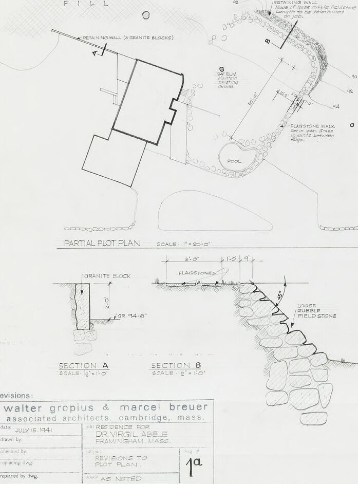
This is an architectural drawing, more specifically a partial plot plan along with sectional details (Section A and Section B). The drawing includes a scale for reference, indicating that 1 inch equals 20 feet on the plot plan and different scales for the sections below.
The plot plan shows the layout of a property, with structures, a pool, and walls indicated. The retaining wall materials are noted as "granite blocks" and "loose double fieldstone". The path around the property is marked as a "Flagstone Walk."
In the lower half of the image, there are two sectional details (A and B) that show the construction of the walls with dimensions -- for example, Section A shows a granite block with the dimensions "8'-0" and Section B appears to detail a section of the retaining wall with layers labeled "loose double fieldstone".
In the revisions note block, the drawing mentions "Revisions to Plot Plan" and is attributed to "walter gropius & marcel breuer associated architects, cambridge, mass." with a job number and name, "RESIDENCE FOR DR.VIRGIL ABELE FRAMINGHAM, MASS." with the date of July 15, 1941. It also includes administrative details regarding the drafting and revisions of the plan.
Created by gpt-4o-2024-05-13 on 2025-03-08
The image is an architectural drawing labeled "PARTIAL PLOT PLAN." It appears to be a plan for modifications to a residence.
Key elements and notes are:
- The drawing includes a scale of 1/4" = 1'–0" for the plot plan.
- There is a detailed depiction of a building surrounded by landscaped features such as a retaining wall, a flagstone walk, and a pool.
- The building is depicted with a simple layout featuring several angles and extensions.
- The upper section of the drawing indicates a "RETAINING WALL (3 GRANITE BLOCKS)" and another "RETAINING WALL (Made of loose rubble fieldstone Length to be determined at job)."
- Various measurements (angles and lengths) are provided for precision construction.
- Detailed sections at the bottom labeled SECTION A and SECTION B, both scaled at 1/2" = 1'–0", show cross-sectional views of the retaining walls and flagstones.
- The drawing specifies materials such as granite block, fieldstone, and flagstones.
- The bottom left contains a box with revisions information, dating July 15, 1941. The architects mentioned are Walter Gropius & Marcel Breuer, who are associated with Cambridge, Mass.
- The project is described as a residence for Dr. Virgil Abele located in Framingham, Mass.
- It also notes "REVISIONS TO PLOT PLAN" and "AS NOTED."
Overall, the drawing provides detailed architectural plans and revisions for outdoor features of a residential property.
Anthropic Claude
Created by us.anthropic.claude-3-5-sonnet-20241022-v2:0 on 2025-06-24
This is an architectural drawing/plot plan created by Walter Gropius & Marcel Breuer Associated Architects from Cambridge, Massachusetts, dated July 15, 1941. The drawing shows a partial plot plan for what appears to be a residential property. The plan includes:
- A house footprint with various setbacks and projections
- A swimming pool
- A retaining wall
- A flagstone walk
- Existing elements like an elm tree
- Various landscaping features
The drawing also includes two detailed sections labeled "Section A" and "Section B" which show construction details for:
- Granite block installation
- Flagstone placement
- Loose/rubble field stone construction
The scale of the main plot plan is 1"=20'-0", and the sections are drawn at 1/2"=1'-0". The drawing appears to be for a residence plan for "Dr. Virgil Abele" in Framingham, Mass. This is noted as drawing number 1a and includes space for revisions.
The drawing demonstrates the precise technical and detailed nature of architectural documentation from this period, showing both the overall site layout and specific construction details.
Created by claude-3-haiku-20240307 on 2024-12-31
This image appears to be an architectural plan or technical drawing. It shows a partial plot plan for a residential or landscape design. The plan includes various features such as a retaining wall made of granite blocks, a pool, a flagstone walk, and additional landscaping elements. The drawing also includes sectional views labeled "Section A" and "Section B" that provide more detailed information about the construction and materials used. Overall, this image seems to be a technical document related to the design and planning of an outdoor area or landscape.
Created by claude-3-5-sonnet-20241022 on 2024-12-31
This is an architectural drawing showing a partial plot plan and construction details from 1941. The drawing was created by Walter Gropius & Marcel Breuer Associated Architects of Cambridge, Massachusetts. The plan shows a residential property layout including:
- A building footprint
- A swimming pool
- A flagstone walk
- Retaining walls made of granite blocks
- An existing elm tree
- Various landscape elements
The drawing also includes two detailed sections (A and B) showing construction specifications for:
- Granite block retaining wall installation
- Flagstone walkway construction
- Field stone wall construction
The scale of the main plot plan is 1"=20'-0", while the sections are drawn at 1/2"=1'-0". This appears to be a renovation or landscape design plan for a residential property in Framingham, Massachusetts. The drawing is numbered 1a and includes spaces for various revision notes at the bottom of the sheet.
Meta Llama
Created by us.meta.llama3-2-11b-instruct-v1:0 on 2025-03-15
The image presents a detailed architectural plan, showcasing a partial plot plan and section views of a property. The plan is divided into two main sections: the top section features a partial plot plan, while the bottom section displays section views.
Partial Plot Plan:
- The partial plot plan is situated at the top of the image.
- It includes a scale of 1" = 20'0".
- The plan is labeled "PARTIAL PLOT PLAN" and features a key with various symbols and abbreviations.
- The plan appears to be a hand-drawn sketch, with some areas shaded or highlighted for emphasis.
Section Views:
- The section views are located at the bottom of the image.
- There are two section views, labeled "SECTION A" and "SECTION B".
- Each section view includes a scale of 1/2" = 1'-0".
- The section views appear to be detailed drawings of specific areas of the property, such as walls, foundations, and other structural elements.
Additional Details:
- In the bottom-left corner of the image, there is a box labeled "revisions:" with a date of July 15, 1941.
- Below the box, there is a list of revisions made to the plan, including changes to the scale and the addition of new features.
- In the bottom-right corner of the image, there is a box labeled "1a" with a note that reads "REVISIONS TO PLOT PLAN".
- The background of the image is a light gray color, with a subtle texture that resembles graph paper.
Overall, the image provides a detailed and informative architectural plan for a property, including a partial plot plan and section views. The plan appears to be a hand-drawn sketch, with some areas shaded or highlighted for emphasis. The additional details in the image provide context and clarity to the plan, making it easier to understand and interpret.
Created by us.meta.llama3-2-90b-instruct-v1:0 on 2025-03-15
This image is a black-and-white architectural drawing of a partial plot plan, featuring a retaining wall and a pool. The top half of the image displays the plot plan, with the retaining wall and pool prominently featured. The bottom half of the image shows two sections of the retaining wall, labeled "Section A" and "Section B." The drawing includes various annotations and measurements, providing detailed information about the design and construction of the retaining wall and pool.
The image appears to be a technical drawing created by an architect or engineer, likely for use in the design and construction of a residential or commercial property. The level of detail and precision in the drawing suggests that it was intended for use by professionals in the field, rather than for general public consumption. Overall, the image provides a clear and concise visual representation of the design and layout of the retaining wall and pool, making it a useful tool for architects, engineers, and contractors working on similar projects.
Amazon Nova
Created by amazon.nova-lite-v1:0 on 2025-01-13
The image is a partial plot plan for a residence in Cambridge, Massachusetts, designed by Walter Gropius and Marcel Breuer, with revisions made by Dr. Virgil Abele. The plan includes details such as the location of a retaining wall made of granite blocks, a pool, and a flagstone walk. The plan also shows the use of loose rubble fieldstone and granite blocks in the construction. The plan is drawn to scale, with a scale of 1 inch equal to 20 feet, and includes sections A and B for further detail. The image also includes notes on the revisions made to the plot plan, including the replacement of a drawing and the addition of notes.
Created by amazon.nova-pro-v1:0 on 2025-01-13
The image is a partial plot plan, a detailed architectural drawing that outlines the layout and design of a specific area, likely a residential or garden space. The plan includes various elements such as retaining walls, flagstone walks, and a pool area. The drawing is annotated with measurements, material specifications, and construction details. It also includes a legend that explains the symbols and abbreviations used in the plan. The plan is dated July 15, 1941, and is attributed to Walter Gropius and Marcel Breuer, renowned architects associated with the Bauhaus movement. The drawing is a technical document that would be used by contractors and builders to construct the space as designed.
Google Gemini
Created by gemini-2.0-flash on 2025-05-12
Here is a description of the image:
The image is a black-and-white architectural drawing, specifically a partial plot plan and sections, likely for a residential property. It's dated July 15, 1941, and attributed to Walter Gropius and Marcel Breuer, associated architects in Cambridge, Massachusetts. The drawing is titled "Revisions to Plot Plan" and indicates a residence for Dr. Virgil Abele in Framingham, Mass.
The partial plot plan, drawn at a scale of 1" = 20'-0", shows a building with a distinct architectural style, a pool, retaining walls, and a flagstone walk. There's also a notation about a 24" elm tree to maintain. The areas are labeled as "FILL" and the drawing indicates retaining walls made of granite blocks and loose rubble fieldstone.
Below the plot plan are two sectional drawings, labeled "Section A" and "Section B," both drawn at a scale of 1/2" = 1'-0". Section A shows a granite block retaining wall, and Section B shows a retaining wall made of loose rubble fieldstone. These sections provide more detailed information about the construction of the retaining walls.
The drawing includes specific dimensions, notes on materials, and labels, indicating it's a technical drawing intended for construction or design purposes.
Created by gemini-2.0-flash-lite on 2025-05-12
Here's a description of the image:
Overall:
The image is an architectural drawing, likely a partial plot plan for a residential property. It appears to be a hand-drawn blueprint, featuring a top-down view of the site and detailed sectional views of certain elements like retaining walls. The drawing is dated July 15, 1941, and is credited to "walter gropius & marcel breuer, associated architects" indicating these were the architects responsible for the design.
Key Elements:
- Partial Plot Plan: The main portion of the drawing is a top-down view of the property, showing the layout of the house, a pool, and the surrounding landscaping.
- House: The outline of the house is depicted with thick, black lines, with a simple rectangular shape. The design appears to be modern or minimalist.
- Pool: A circular or kidney-shaped pool is shown, adjacent to the house.
- Landscaping and Retaining Walls: The landscape includes a retaining wall made of loose rubble fieldstone on the upper right corner, and some flagstone.
- Sectional Views: There are two detailed sectional views:
- Section A: Shows a retaining wall constructed with granite blocks.
- Section B: Shows a retaining wall made with loose rubble fieldstone with flagstones.
- Labeling and Annotations: The drawing is carefully labeled, providing essential information about the design and construction. There are also notes indicating materials, dimensions, and other details.
Style and Quality:
The drawing style is clean, with a classic blueprint aesthetic. The lines are clear, and the level of detail is practical for construction purposes. It reflects the design sensibilities of the time.
Conclusion:
The image is a valuable document providing insight into the architectural vision and the property's design. It showcases architectural detailing for a residence of Dr. Virgil Abele in Framingham, Massachusetts.
Mistral Pixtral
Created by us.mistral.pixtral-large-2502-v1:0 on 2025-05-31
The image is an architectural drawing that includes a partial plot plan and two sectional views labeled "Section A" and "Section B." The drawing is dated July 15, 1941, and was prepared by Walter Gropius and Marcel Breuer, associated architects from Cambridge, Massachusetts, for Mr. and Mrs. Bryce LeBelle of Wellesley, Massachusetts.
Partial Plot Plan:
- Scale: 1" = 20'-0"
- Features:
- A house with a distinctive angular design.
- A pool located to the right of the house.
- A retaining wall made of granite blocks.
- A flagstone walk leading to the pool area.
- Various annotations indicating dimensions and materials.
Section A:
- Scale: 1/2" = 1'-0"
- Details:
- Shows a cross-section of the retaining wall made of granite blocks.
- Indicates the height and depth of the granite blocks.
- Shows the placement of flagstones on top of the granite blocks.
Section B:
- Scale: 1/2" = 1'-0"
- Details:
- Illustrates a cross-section of a fieldstone wall.
- Shows the arrangement and layering of the fieldstones.
- Indicates the height and depth of the fieldstone wall.
Additional Information:
- The drawing includes a note indicating that it was drawn by "B.V.L." and checked by "W.G."
- There is a reference to revisions to the plot plan.
- The drawing is labeled as "1a."
This detailed architectural drawing provides a clear layout and cross-sectional views of the proposed construction, including specific materials and dimensions for the retaining walls and walkways.
Qwen
Created by Qwen/Qwen2.5-VL-7B-Instruct on 2025-07-20
The image is a detailed architectural drawing of a partial plot plan. It includes a scale and several annotations indicating the design and layout of a landscape feature, likely for a residential property. Here are the key elements visible in the image:
Partial Plot Plan:
- Building Footprint: The main structure is outlined at the center-left, with dimensions and angles indicated.
- Retaining Walls:
- A retaining wall is shown at the top-left corner, labeled as "RETAINING WALL (2 GRANITE BLOCKS)".
- Another retaining wall is shown at the bottom, labeled as "RETAINING WALL" and "LOOSE RUBBLE FIELD STONE".
- Pool: A circular area labeled as "POOL" is located in the center-right.
- Elm Tree: An "ELM" tree is marked within the existing grade near the top of the drawing.
- Flagstone Walk: A labeled path made of flagstones is shown leading to the pool.
- Grading: The terrain is depicted with elevation changes, indicated by "EXISTING GRADE".
Sectional Views:
- Section A: A close-up view of a granite block.
- Section B: A detailed view of the loose rubble fieldstone retaining wall.
Annotations and Labels:
- Scale: The drawing is scaled at 1" = 20'-0" for the plan view and 1/2" = 1'-0" for the sectional views.
- Revisions: The document is marked as revisions to a plot plan, with revisions noted to include "AS NOTED".
Workplace and Client Information:
- The drawing is attributed to Walter Gropius & Marcel Breuer, Associated Architects, located in Cambridge, Mass.
- The project is for a residence for Dr. Virgil Abele in Framingham, Mass.
- The date of the drawing is July 15, 1941.
This appears to be a professional architectural blueprint for the landscaping and structural elements of a house.
Created by Qwen/Qwen2.5-VL-72B-Instruct on 2025-07-20
This image is a detailed architectural drawing of a partial plot plan and associated sections for a residential property. The plan includes the following elements:
Partial Plot Plan:
- The scale is indicated as 1" = 20'-0".
- The drawing shows a rectangular building with an irregular extension on one side.
- There are two retaining walls labeled:
- One made of granite blocks.
- Another made of loose rubble fieldstone, with the length to be determined on the job.
- A flagstone walk set in lean grout is shown leading to a pool area.
- The pool is irregularly shaped and located near the retaining wall.
- An elm tree is indicated with a note mentioning "Mountain Gravel Grade."
Sections A and B:
- Section A shows a cross-section of the granite block retaining wall with dimensions and a detail note "GR 94-6."
- Section B shows a cross-section of the loose rubble fieldstone retaining wall with dimensions and details.
Additional Notes and Information:
- The drawing is labeled as a revision to the plot plan.
- It is dated July 15, 1941, and is for the residence of Dr. Virgil Abele in Framingham, Massachusetts.
- The architects are Walter Gropius & Marcel Breuer, associated architects from Cambridge, Massachusetts.
The drawing is detailed and includes various annotations and scale indications to provide a comprehensive view of the planned landscaping and construction details for the property.
Text analysis
Amazon