
Machine Generated Data
Tags
Color Analysis
Feature analysis
Amazon
Clarifai
AWS Rekognition
| Monitor | 96.1% | |

Categories
Imagga
created on 2022-06-04
| interior objects | 56.5% | |
| text visuals | 41% | |
Captions
Microsoft
created by unknown on 2022-06-04
| a flat screen tv sitting on top of a desk | 45.9% | |
| a flat screen tv sitting on top of a table | 34.4% | |
| a flat screen tv | 34.3% | |
Clarifai
No captions written
Salesforce
Created by general-english-image-caption-blip on 2025-05-21
a photograph of a black and white photo of a black and white photo of a black and white
Created by general-english-image-caption-blip-2 on 2025-07-02
a black and white photo of a blueprint
OpenAI GPT
Created by gpt-4 on 2024-12-07
This image depicts a series of technical architectural drawings or blueprints. The drawings show various detailed sections and components such as wall panels, door frames, buttresses, columns, and more. These designs may represent parts of a building and are used to guide construction or engineering projects. Annotations and dimensions are included to provide specifications for how each part should be constructed.
There's a white border around the image suggesting that it's a photograph of the original blueprint document. Additionally, there's a number on the bottom right corner, "99.3," which could likely be a reference or archive number. The contrast in the image is high, featuring white or light lines and text on a dark background, which is characteristic of the style of negatives or certain types of reproduction processes for blueprints.
Created by gpt-4o-2024-05-13 on 2024-12-07
The image is a black and white photograph of an architectural or engineering drawing. The drawing appears to show detailed plans of wall sections, labeled as "Horizontal Section Through Sloping Sash," "Horizontal Section at Corner," "Full Size Detail of Wall Panel Showing Connector and Wedge in Place," among other views. It includes intricate details of the connections and measurements, including terms like "Exterior Covering," "Wall Frame," "Connector," "Wedge," "Siding," and "Seal Strip."
There are specific notations and technical terms throughout the drawing, indicating detailed engineering specifications. It is noted that the drawing is prepared by "General Panel Corp., New York," and the drawing number is indicated as "3" with a date marked as "Sept 26, 1950 B."
The photograph is mounted or placed within a framed background, which is visible around the edges. There is also a handwritten number "99.3" at the bottom right corner of the frame.
Anthropic Claude
Created by us.anthropic.claude-3-5-sonnet-20241022-v2:0 on 2025-06-25
This appears to be an architectural or engineering blueprint/technical drawing showing horizontal wall sections and details. The image is in black and white (appears to be a negative) and shows various cross-sectional views of what seems to be sliding sash and wall panel components. There are detailed drawings of connectors, frames, and other structural elements. The drawing includes measurements and technical specifications, with multiple views showing different aspects of the construction. At the bottom of the drawing, there appears to be a title block with what looks like drawing information and numbers. The drawing is labeled as showing "FULL SIZE DETAIL OF WALL PANEL SHOWING CONNECTOR AND MULLION." The overall document appears to be a professional technical specification drawing, possibly for construction or manufacturing purposes.
Created by claude-3-haiku-20240307 on 2024-12-07
The image appears to be an architectural or engineering drawing or blueprint. It shows detailed schematics and diagrams of a wall panel or wall section, including various dimensions, measurements, and technical specifications. The drawing appears to be in black and white, with intricate lines and labels indicating the different components and structural elements of the wall panel.
Created by claude-3-5-sonnet-20241022 on 2024-12-07
This appears to be an architectural or engineering technical drawing showing horizontal wall sections and details. The image is a blueprint-style drawing with white lines on a dark background. It includes several cross-sectional views and details of what appears to be sliding door or window mechanisms, wall panels, and connectors. There are horizontal sections showing various components like wall frames and sliding sash elements. At the bottom of the drawing, there's a detailed view labeled as "FULL SIZE DETAIL OF WALL PANEL SHOWING CONNECTOR AND HEAD CAP." The drawing appears to be professionally drafted with precise technical specifications and measurements. There's a title block in the lower right corner that seems to be from General Panel Corporation and has the number "3" visible.
Meta Llama
Created by us.meta.llama3-2-11b-instruct-v1:0 on 2024-12-07
The image presents a black-and-white blueprint for a wall panel, showcasing its design and components. The blueprint is set against a white background, surrounded by a thick black border, and features a handwritten number "99.3" in the bottom-right corner.
Key Features:
- Wall Panel Design: The blueprint illustrates the wall panel's layout, including its dimensions and various components such as the door frame, wall frame, and connector.
- Components: The blueprint labels each component, providing a clear understanding of the wall panel's structure.
- Dimensions: The blueprint includes measurements for the wall panel, allowing for precise construction or installation.
- Handwritten Number: The handwritten number "99.3" in the bottom-right corner suggests that this may be a unique identifier or reference number for the blueprint.
Overall Impression:
The image appears to be a technical drawing or blueprint for a wall panel, likely used in construction or architectural projects. The level of detail and precision in the drawing suggests that it was created for a specific purpose, such as building or renovating a structure.
Created by us.meta.llama3-2-90b-instruct-v1:0 on 2024-12-07
The image presents a technical drawing of a wall panel, showcasing its various components and their relationships. The drawing is rendered in white on a black background, with a white border surrounding it. The panel's details are meticulously labeled, providing a clear understanding of its structure.
Key Features:
- Wall Panel: The central element of the drawing, comprising multiple sections that work together to form a cohesive unit.
- Labels: Each component is carefully labeled, allowing for easy identification and comprehension of the panel's design.
- Sectional Views: The drawing includes sectional views, offering a detailed look at the panel's internal structure and how its components interact.
- Dimensions: Although not explicitly stated, the drawing likely includes dimensions to ensure accurate construction and assembly of the wall panel.
Conclusion:
In summary, this technical drawing provides a comprehensive overview of a wall panel's design, highlighting its key components and their relationships. The use of labels, sectional views, and dimensions enables a thorough understanding of the panel's structure, making it an essential resource for construction and assembly purposes.
Amazon Nova
Created by amazon.nova-lite-v1:0 on 2025-02-27
This image is a technical drawing of a wall panel, showing various sections and details of the panel. The drawing is labeled "Full Size Detail of Wall Panel Showing Connector and Wedge Place," indicating that it provides a detailed view of the wall panel, including the connector and wedge placement.
The drawing is divided into several sections, including a horizontal section at the top, a horizontal section at a typical wall, and a horizontal section at a buttress and column. The drawing also includes a vertical section at a corner, showing the details of the wall panel at the corner.
The drawing is labeled with various measurements and dimensions, including the size of the wall frame, the thickness of the exterior covering, and the size of the cover strip. The drawing also includes notes on the installation of the wall panel, including the placement of the connector and wedge.
Overall, the image provides a detailed and technical view of a wall panel, showing the various components and details involved in its construction and installation. The drawing is likely used by architects, engineers, and construction professionals to ensure that the wall panel is installed correctly and meets the required specifications.
Created by amazon.nova-pro-v1:0 on 2025-02-27
The image is a technical drawing or blueprint of a wall panel, likely for construction or architectural purposes. The drawing is on a black background with white lines and text, typical of architectural plans. It includes various sections and details of the wall panel, such as "EXTERIOR COVERING," "INTERIOR COVERING," "HORIZONTAL SECTION AT CORNER," and "VERTICAL SECTION AT BUTTRESS AND COLUMN." There are also dimensions, measurements, and labels indicating different parts of the wall panel, such as "WALL FRAME," "WALL PANEL," and "CONNECTOR." The drawing also includes a reference to "GENERAL PANEL CORP" and "GRAYBAR BUILDING NEW YORK," suggesting that it is a specific design for a project in New York. The drawing is labeled "99.3," possibly indicating a page number or section within a larger set of plans.
Google Gemini
Created by gemini-2.0-flash on 2025-05-18
Here is a description of the image:
The image shows a black and white architectural drawing framed in black. The drawing depicts several cross-sectional views of wall panel construction, possibly from a manual.
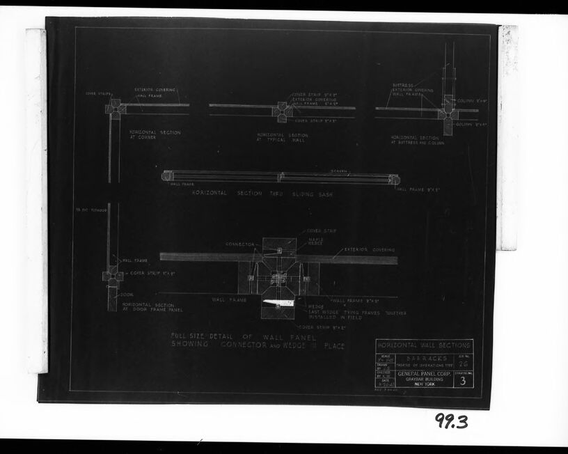
The drawing's main title is “FULL SIZE DETAIL OF WALL PANEL SHOWING CONNECTOR AND WEDGE IN PLACE”. Above this are several sectional views of the wall. These include “HORIZONTAL SECTION AT CORNER”, “HORIZONTAL SECTION AT TYPICAL WALL”, “HORIZONTAL SECTION THRU SLIDING SASH”, and “HORIZONTAL SECTION AT DOOR FRAME PANEL”. There is also one section labeled “HORIZONTAL SECTION AT BUTTRESS AND COLUMN”.
The drawing has details such as "COVER STRIP", "EXTERIOR COVERING", "WALL FRAME", "CONNECTOR", "WEDGE", and "BUTTRESS" clearly labeled, indicating the different components of the wall.
In the lower right corner of the drawing, there is a section labeled "HORIZONTAL WALL SECTIONS" along with the company name "GENERAL PANEL CORP,". The project name is "BARRACKS". The drawing also includes scale information and a number.
Created by gemini-2.0-flash-lite on 2025-05-18
This is a detailed architectural drawing, likely a blueprint, showing various horizontal wall sections. The drawing appears to be for a building or structure and depicts the construction details of the wall panels, including the frames, cover strips, and connections. Key features labeled include "Exterior Covering", "Wall Frame", "Connector", and "Wedge". The drawing is titled "Full Size Detail of Wall Panel Showing Connector and Wedge in Place". There are also horizontal sections at different points like the corner, a typical wall, and at the door frame panel, as well as a detailed section of the sliding sash. It also includes details for the "Buttress" and "Column" and indicates the scale. The drawing belongs to a series of "Horizontal Wall Sections" and is from General Panel Corp in New York. The drawing has been marked with the number "3" and possibly refers to blueprints from the Barracks.
Mistral Pixtral
Created by us.mistral.pixtral-large-2502-v1:0 on 2025-06-03
The image is a detailed architectural blueprint showing various sections and details of a wall panel system. The drawing is labeled "Full Size Detail of Wall Panel Showing Connector and Wedge in Place." It includes multiple views and sections to illustrate how different components of the wall panel system are assembled.
Key elements shown in the blueprint include:
Horizontal and Vertical Sections:
- The blueprint provides horizontal and vertical sections at different points such as the corner, typical wall, and sliding sash.
- These sections show the internal structure and how the wall frames, studs, and coverings are arranged.
Components:
- Wall Frame: The primary structural element of the wall panel.
- Exterior Covering: The outer layer of the wall panel.
- Interior Covering: The inner layer of the wall panel.
- Connector: A component used to join different parts of the wall panel system.
- Wedge: A piece used to secure the connector in place.
- Steel Stud: A vertical structural member within the wall frame.
- Buttress: A support structure integrated into the wall system.
Dimensions and Specifications:
- The blueprint includes specific measurements and dimensions for various components and their placements.
- For example, the steel stud is noted to be 3-5/8 inches, and the connector has specific dimensions provided.
Materials:
- The blueprint specifies the materials used, such as 22 gauge black steel for the wall frame and connectors.
Manufacturer Information:
- The blueprint is credited to General Panel Corp., with an address in New York City.
- The drawing number is 99.3.
Overall, the blueprint provides a comprehensive guide for the assembly and construction of a wall panel system, detailing the arrangement and connection of various components.
Qwen
Created by Qwen/Qwen2.5-VL-7B-Instruct on 2025-07-26
The image is a technical drawing or blueprint that appears to detail the construction of a wall panel, specifically from a Barracks project by the General Panel Corp. The drawing includes several labeled sections and annotations, providing a detailed view of different components and their relationships within the wall structure.
Title Block: At the bottom right corner, there is a title block that includes the project name "BARRACKS," the number "26," and the company name "GENERAL PANEL CORP." Additional text includes "GENERAL CONTRACTORS," "NEW YORK," and "BARRACKS," possibly indicating a specific section or model number.
Annotations: The drawing includes various annotations and labels, such as "WALL FRAME," "DOOR," "GATEFRONT COVERING," "WALL PANEL," "EXTREME OPENING," "COLUMN," "WALL FRAME," "SLIDING SASH," "CONNECTOR," "WALL FRAME," "DOOR FRAME PANEL," "HORIZONTAL SECTION AT CORNER," "HORIZONTAL SECTION AT DOOR FRAME PANEL," and "HORIZONTAL SECTION AT WALL."
Sections: The drawing shows horizontal sections of the wall structure, labeled at various points. These sections are marked with "HORIZONTAL SECTION AT CORNER," "HORIZONTAL SECTION AT DOOR FRAME PANEL," and "HORIZONTAL SECTION AT WALL," among others. These sections are interconnected with other components, such as the wall frame, door, and sliding sash.
Connector and Wedge: The bottom section of the drawing is labeled "FULL SIZE DETAIL OF WALL PANEL SHOWING CONNECTOR AND WEDGE IN PLACE," which seems to provide a detailed view of how the wall panel is constructed, including the installation of a connector and wedge.
Dimensions: While specific dimensions are not clearly visible in the image, the drawing suggests that the wall panels are designed with a precise measurement system, as indicated by the 5" x 8" dimensions mentioned.
Overall: The image is a technical and structured blueprint, likely intended for architects, contractors, or engineers working on the Barracks project by the General Panel Corp. The drawing provides a comprehensive view of the wall panel's components and their arrangement, which is essential for construction purposes.
Created by Qwen/Qwen2.5-VL-72B-Instruct on 2025-07-26
The image is a black and white blueprint or detailed engineering drawing for building components, specifically wall panels and their various sections. The drawing shows multiple horizontal cross-sections of the wall panels, detailing how they are constructed and assembled. Key elements include:
- Horizontal Sections: The drawing includes several horizontal sections labeled as "Horizontal Section at Corner," "Horizontal Section at Typical Wall," and "Horizontal Section at Buttress and Column." These sections show the internal structure of the walls, including the framing, insulation, and connections.
- Wall Panel Details: There is a full-size detail of a wall panel showing how the connector and wedge are placed. This detail includes labels for different parts like the cover strip, wall frame, and wedge.
- Sliding Sash: There is a section labeled "Horizontal Section thru Sliding Sash," which shows the integration of a sliding window within the wall panel.
- Door Frame Panel: Another section labeled "Horizontal Section at Door Frame Panel" shows how a door is integrated into the wall panel.
- Labels and Annotations: The drawing is filled with numerous labels and annotations that provide specific information about each component and its placement. For example, there are labels for "Cover Strip," "Wall Frame," "Wedge," and "Last Wedge Tying Frame Together."
- General Information: The drawing includes a title block in the bottom right corner that provides general information about the drawing, such as the title "Horizontal Wall Sections," the scale, and the company name "General Panel Corp."
The drawing is meticulously detailed, providing clear instructions for the construction and assembly of the wall panels. The overall layout is organized, with each section clearly labeled and easy to follow.
Text analysis
Amazon


