Machine Generated Data
Tags
Color Analysis
Feature analysis
Amazon
Clarifai
AWS Rekognition
| Monitor | 88.7% | |

Categories
Imagga
created on 2022-06-04
| text visuals | 70.2% | |
| interior objects | 17.2% | |
| streetview architecture | 7.1% | |
| paintings art | 2.2% | |
| cars vehicles | 1.5% | |
Captions
Microsoft
created by unknown on 2022-06-04
| a screen shot of a window | 51.8% | |
| a screen shot of a television | 35% | |
| a screen shot of a large window | 34.9% | |
Clarifai
No captions written
Salesforce
Created by general-english-image-caption-blip-2 on 2025-06-29
a black and white drawing of a building with a plan
Created by general-english-image-caption-blip on 2025-05-03
a photograph of a black and white photo of a black and white drawing of a building
OpenAI GPT
Created by gpt-4 on 2024-12-07
The image shows a blueprint featuring a technical drawing. It is predominantly in a white-on-black color scheme, which indicates that it might be a negative or a specific type of photocopy. The blueprint includes several detailed diagrams and annotations, suggesting that it is a design or plan for some sort of mechanical or architectural project. There are several sections labeled with measurements and specifications.
In the lower right corner, there is a text box that seems to contain additional information about the project, like a title or description, and possibly the scale, but it is not clearly readable in the given resolution. The project seems complex, with multiple layers and components indicated by the various lines, shapes, and symbols throughout the drawing.
Created by gpt-4o-2024-05-13 on 2024-12-07
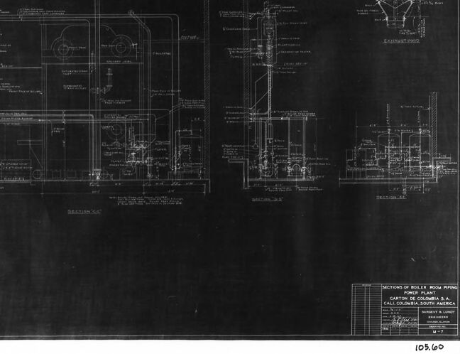
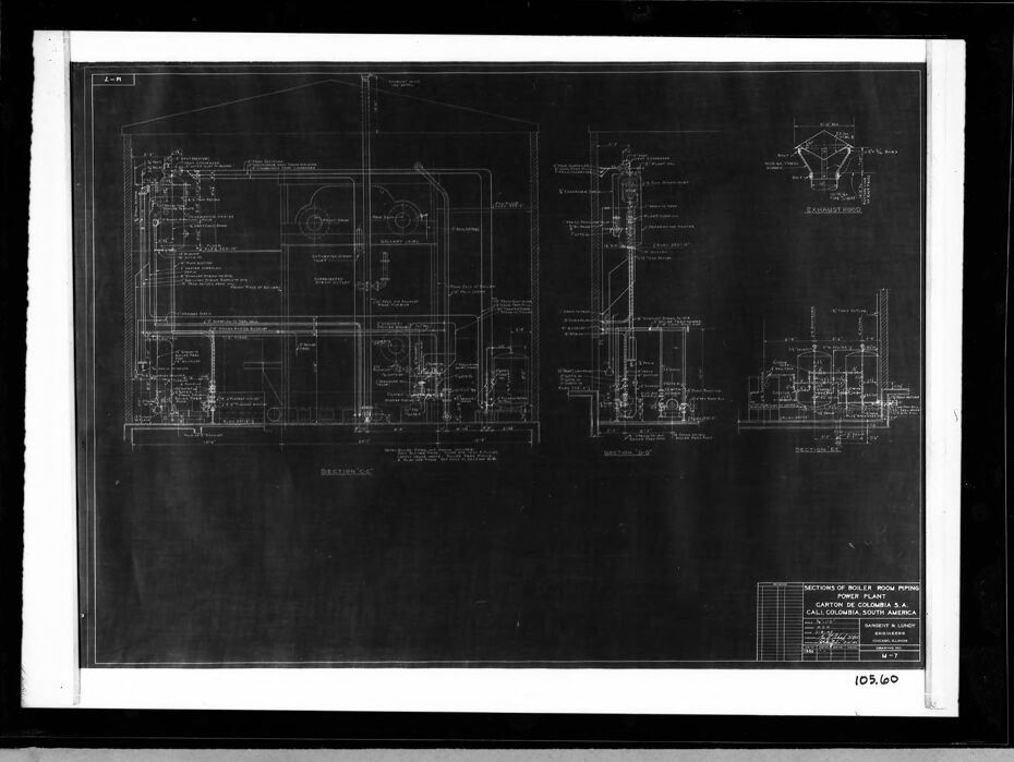
The image contains a detailed technical blueprint or engineering drawing. It showcases sections of piping and boiler room schematics for a plant, specifically labeled "Piper Plant #2." The title block at the bottom right corner identifies the purpose of the blueprint and provides some specific details: "Sections of Boiler Room Piping - Piper Plant #2, Carton de Colombia S. A., Cali, Colombia, South America." Additionally, the blueprint is prepared by "Kaiser Engineers Inc." with a drawing number of "04-08-368."
The drawing appears to be a part of construction or engineering plans, likely used for industrial or mechanical purposes. The blueprint itself is detailed with measurements, labels, and different views of the piping sections and boiler room layouts.
Anthropic Claude
Created by us.anthropic.claude-3-5-sonnet-20241022-v2:0 on 2025-06-25
This image appears to be a technical blueprint or engineering drawing, shown as white lines on a dark background (likely a negative/inverted image). It appears to be some kind of industrial or power plant schematic, with various interconnected systems, pipes, and components shown in detailed technical drawings. The drawing includes multiple annotations and measurements, and appears to be quite complex and detailed. The layout suggests this might be for a power generation facility or similar industrial installation. The drawing has a title block in the bottom corner, which is standard for engineering drawings, though the text is not clearly legible in this image.
Created by claude-3-haiku-20240307 on 2024-12-07
The image appears to be a detailed technical blueprint or engineering schematic. It contains various diagrams, labels, and numerical information, all rendered in a stark black-and-white style. The overall layout suggests this is a detailed technical drawing or construction plan, likely for some kind of industrial or mechanical equipment. Without being able to identify any specific individuals, the image seems to depict complex technical specifications and engineering schematics.
Created by claude-3-5-sonnet-20241022 on 2024-12-07
This appears to be an architectural or engineering blueprint/drawing, shown as a negative (white lines on black background). It appears to be a technical drawing showing sectional views of what seems to be part of a power plant or industrial facility. The drawing includes detailed cross-sections and various technical specifications, with multiple views showing different aspects or angles of the structure. You can see various annotations and measurements throughout the drawing, typical of professional engineering documentation. The image number "105.60" is visible in the corner, suggesting this is part of a larger set of technical drawings.
Meta Llama
Created by us.meta.llama3-2-11b-instruct-v1:0 on 2024-12-07
The image presents a technical drawing of a boiler room piping power plan, showcasing the intricate details of the system's layout and components. The drawing is rendered in white on a black background, with a white border surrounding it, and is set against a gray background.
Key Features:
- Title: "SECTIONS OF BOILER ROOM PIPING POWER PLAN" is written in the bottom-right corner.
- Scale: The scale is indicated as 1/8" = 1'-0".
- Dimensions: The drawing measures 105.60 inches in length.
- Components: Various components are labeled, including boilers, pumps, valves, and pipes, providing a comprehensive overview of the system's design and functionality.
- Layout: The drawing depicts the boiler room piping power plan in a detailed and organized manner, allowing for easy identification of each component and its relationship to others.
Conclusion:
The image provides a clear and concise visual representation of the boiler room piping power plan, making it an essential tool for engineers, architects, and other professionals involved in the design and implementation of such systems. The level of detail and organization in the drawing suggests that it was created for a specific purpose, such as a project proposal or a technical specification document. Overall, the image is a valuable resource for anyone seeking to understand the intricacies of boiler room piping power plans.
Created by us.meta.llama3-2-90b-instruct-v1:0 on 2024-12-07
The image presents a technical drawing of a boiler room piping power plant, showcasing the intricate details of its design. The drawing is rendered in white on a black background, with a white border surrounding it and a black border outside that. The overall effect is one of precision and attention to detail, highlighting the complexity of the system.
Key Features:
- Technical Drawing: The image features a technical drawing of a boiler room piping power plant, showcasing the intricate details of its design.
- White on Black Background: The drawing is rendered in white on a black background, creating a striking visual contrast.
- White Border: A white border surrounds the drawing, adding a touch of elegance to the overall design.
- Black Border: A black border outside the white border provides a sense of depth and dimensionality to the image.
- Precision and Attention to Detail: The drawing highlights the complexity of the system, demonstrating the precision and attention to detail required in its design.
Conclusion:
In conclusion, the image presents a technical drawing of a boiler room piping power plant, showcasing the intricate details of its design. The use of white on a black background, combined with the white and black borders, creates a visually striking image that highlights the complexity of the system. The precision and attention to detail evident in the drawing demonstrate the importance of careful planning and execution in the design of such systems.
Amazon Nova
Created by amazon.nova-lite-v1:0 on 2025-02-25
The image is a technical drawing or blueprint, typically used in engineering or architectural contexts. It features a large, detailed diagram on a black background, likely representing a mechanical or structural design. The drawing is divided into sections, with each section containing various components, pipes, and annotations. The text "SECTIONS OF BOILER ROOM PIPING" at the bottom suggests that this blueprint is for a boiler room, detailing the piping layout. The drawing includes labels, dimensions, and possibly notes on materials and specifications. The overall design is complex, indicating a sophisticated system.
Created by amazon.nova-pro-v1:0 on 2025-02-25
The image depicts a technical drawing or blueprint of a boiler room piping system. The drawing is presented on a black background with white lines and text, likely created using a CAD program. It features various sections and components of the piping system, including pipes, valves, and other mechanical elements. The drawing includes dimensions, labels, and annotations to provide detailed information about the system's layout and specifications.
Google Gemini
Created by gemini-2.0-flash-lite on 2025-04-30
This image is a blueprint or technical drawing, likely for a power plant. It depicts detailed sectional views of the boiler room piping.
Key features include:
- Sections: The drawing provides multiple sectional views ("Section CC", "Section FF", etc.) to illustrate the internal layout and components.
- Piping: Numerous pipes and associated components are shown, suggesting the intricate network of steam, water, and potentially other fluids required for the power plant's operation.
- Equipment: There are depictions of various pieces of equipment, like boilers, turbines, and possibly tanks, as well as valves, pumps, and other controls.
- Annotations: The diagram is filled with labels, dimensions, and notes that would guide the construction or maintenance of the power plant system.
- Location: The drawing is identified as pertaining to a power plant in Cali, Colombia, South America.
- Presentation: It is a blueprint with a white drawing on a dark background, and framed.
Created by gemini-2.0-flash on 2025-04-30
Here is a description of the image:
The image appears to be a framed black and white photograph of an engineering blueprint. The blueprint shows detailed schematics of sections of boiler room piping for a power plant in Cali, Colombia, South America. The drawing includes multiple sections, labeled as "SECTION 'CC'," "SECTION 'EE'," and "SECTION 'BB'." Additionally, there is a smaller inset labeled "EXHAUST HOOD." The blueprint includes numerous notes, dimensions, and diagrams of pipes, boilers, and other mechanical components. In the bottom right corner of the blueprint, there is a title block containing information about the project, including the location, the name of the engineering firm (Sargent & Lundy), and a document number (M-7). There is also what appears to be a stamped number at the very bottom: 105.60. The blueprint is framed with a black matte and a black frame.
Mistral Pixtral
Created by us.mistral.pixtral-large-2502-v1:0 on 2025-05-29
The image is a detailed technical blueprint or engineering drawing, likely for a mechanical or industrial system. Here are some specific observations:
Title and Identification:
- The bottom right corner contains the title: "Sections of 600# Steam Piping to 250# Steam Header, Power Plant, California, S.A., Central America."
- The drawing number "10560" is visible at the bottom right.
- The name "Samuel K. Lapp" appears, possibly indicating the engineer or drafter.
Sections:
- The drawing is divided into three main sections labeled "Section A-A," "Section B-B," and "Section C-C."
- Each section appears to show a cross-sectional view of different parts of the piping system.
Details:
- The blueprint includes various technical details such as dimensions, labels for different components, and annotations indicating specific parts of the system.
- There are detailed representations of pipes, valves, flanges, and other mechanical components.
- The layout includes elevation views and possibly some plan views to show the spatial arrangement of the piping system.
Scale and Units:
- The drawing likely uses a specific scale to represent the actual sizes of the components.
- Units of measurement are not explicitly stated but are typically in inches or feet for such drawings.
Purpose:
- The blueprint is intended for the construction, maintenance, or modification of a steam piping system in a power plant located in California, Central America.
- It provides essential information for engineers, technicians, and workers to understand the layout and specifications of the piping system.
Overall, this blueprint is a critical document for the design and implementation of a steam piping system in an industrial setting.
Qwen
Created by Qwen/Qwen2.5-VL-7B-Instruct on 2025-07-27
The image appears to be a technical blueprint or drawing, likely for a piping system design. It includes detailed technical sketches and annotations, possibly indicating different sections or views of the piping system. The labels and numerical annotations suggest specific dimensions and directions for the design. It includes a title or reference at the bottom right, which mentions "CARTON DE COLOMBIA S.A." and "COLOMBIA, SOUTH AMERICA," indicating the project might be related to a facility in this region. The overall layout and style are characteristic of engineering or architectural drawings, used for precise planning and construction.
Created by Qwen/Qwen2.5-VL-72B-Instruct on 2025-07-27
The image appears to be a technical drawing or blueprint, specifically detailing sections of boiler room piping. It is presented on a dark background with white lines and text, which is typical for engineering or architectural plans. The drawing includes various views and details of the piping system, including side views, top views, and possibly cross-sectional views. There are annotations and labels that provide additional information about the components and their dimensions. The text at the bottom right corner indicates that this is related to Carton de Colombia S.A., located in Cali, Colombia, South America. The drawing is labeled with a reference number, "M-7," and another number, "103,60," is visible in the bottom right corner. The overall layout and style suggest that this is a detailed engineering document used for construction or maintenance purposes.
Text analysis
Amazon