
Machine Generated Data
Tags
Color Analysis
Feature analysis
Amazon
Clarifai
AWS Rekognition
| Monitor | 84% | |


Categories
Imagga
created on 2022-06-04
| text visuals | 71% | |
| interior objects | 12.5% | |
| streetview architecture | 7.9% | |
| paintings art | 5.4% | |
| events parties | 1.1% | |
Captions
Microsoft
created by unknown on 2022-06-04
| a flat screen tv sitting on top of a blackboard | 67% | |
| a flat screen television | 66.9% | |
| a flat screen tv sitting on top of a television | 52.3% | |
Clarifai
No captions written
Salesforce
Created by general-english-image-caption-blip on 2025-05-19
a photograph of a black and white photo of a black and white photo of a house plan
Created by general-english-image-caption-blip-2 on 2025-07-02
a black and white drawing of a building
OpenAI GPT
Created by gpt-4 on 2024-12-07
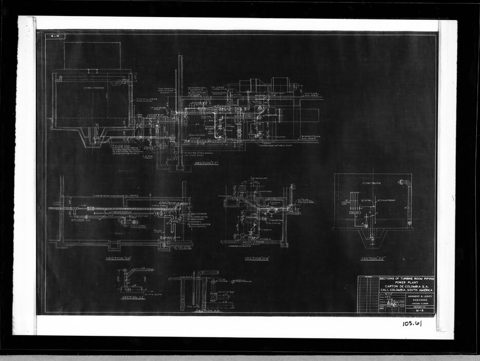
The image provided appears to be a photograph of a blueprint or technical drawing. The drawing is on a black background with white lines, text, and details, which is characteristic of a traditional blueprint. This particular blueprint seems to illustrate a mechanical design containing various views of a machine or complex assembly with numerous components labeled with dimensions and technical notes.
There are sectional views, detailed part drawings, and overall assembly layouts, which provide a comprehensive visual representation of the mechanical system or piece of machinery. It looks like a fairly detailed engineering plan, possibly for something like mechanical equipment, an engine, or industrial machinery. The bottom right corner contains text which is likely the title, specifications, or reference information about the drawing or the project it represents. It mentions "Calcolli, South Africa," suggesting the blueprint might be associated with a project or location there.
Created by gpt-4o-2024-05-13 on 2024-12-07
The image is of a technical engineering blueprint or drawing, displayed horizontally within a frame. The blueprint features multiple detailed diagrams, including sectional views, annotations, and measurements.
In the lower right corner, there is a title block that includes a project title and details, which read as follows:
"Sections of Turbine Room Piping Piping Diagram for Phase 1 Bot Engine Factory for Col. G-874 Agr. S.A. Cali, Colombia, South America." Additional information about the drawing's scale and the engineer or draftsman may be present in this block as well.
The drawing is primarily black with white lines and text, suggesting it might be a reproduction or a traditional blueprint. The white text and lines offer a contrasting view against the dark background, making technical elements visible. Various sectional views are denoted, which seem to represent different machinery or piping systems and their configurations.
Anthropic Claude
Created by us.anthropic.claude-3-5-sonnet-20241022-v2:0 on 2025-06-25
This image appears to be an architectural or engineering blueprint/technical drawing, shown as a black and white negative (white lines on black background). It appears to be showing various cross-sections and detailed plans for what seems to be a power plant, based on the visible title block in the lower right corner. The drawing contains multiple sectional views with various technical details, piping layouts, and dimensional information. The drawing is quite complex with numerous lines, annotations, and technical specifications spread across different sections of the sheet. It's the type of detailed technical document that would be used during construction or engineering planning phases of an industrial facility.
Created by claude-3-haiku-20240307 on 2024-12-07
The image appears to be a detailed engineering or technical blueprint or diagram. It contains various technical drawings, schematics, and diagrams with annotations and labels, but does not depict any human faces or figures. The overall image seems to be focused on engineering or technical specifications and plans, likely related to some kind of industrial or mechanical system.
Created by claude-3-5-sonnet-20241022 on 2024-12-07
This appears to be an architectural or engineering blueprint, specifically a mechanical drawing showing various cross-sections and details of what seems to be a power plant facility. The image is a black and white technical drawing with white lines on a dark background, typical of blueprint reproduction style. The drawing contains multiple detailed sections labeled as "SECTION A-A", "SECTION B-B", etc., showing different views and technical details of the mechanical systems. At the bottom right corner, there appears to be a title block which is standard for engineering drawings. The drawing shows complex piping layouts, mechanical equipment, and structural details through various cross-sectional views. The level of detail suggests this is a professional engineering document likely used for construction or facility planning purposes.
Meta Llama
Created by us.meta.llama3-2-11b-instruct-v1:0 on 2024-12-07
The image presents a technical drawing of a power plant, specifically focusing on the sections of the turbine room piping. The drawing is rendered in white on a black background, with a white border surrounding it. It is set against a gray background, which provides a subtle contrast to the technical details of the drawing.
Key Features:
- Technical Drawing: The drawing is a detailed representation of the power plant's turbine room piping, showcasing various components and their connections.
- White on Black Background: The use of white lines on a black background creates a clear and legible visual representation of the technical information.
- White Border: The white border adds a touch of elegance to the overall design, while also providing a clean and crisp frame for the drawing.
- Gray Background: The gray background serves as a neutral backdrop, allowing the technical details of the drawing to take center stage.
Purpose:
The purpose of this image is likely to provide a clear and concise visual representation of the power plant's turbine room piping for engineering, maintenance, or operational purposes. The level of detail and precision in the drawing suggests that it may be used for planning, design, or troubleshooting activities.
Conclusion:
In conclusion, the image presents a technical drawing of a power plant's turbine room piping, showcasing its various components and connections. The use of a white on black background, white border, and gray background creates a visually appealing and informative image that is likely to be useful for technical purposes.
Created by us.meta.llama3-2-90b-instruct-v1:0 on 2024-12-07
The image presents a detailed blueprint of a turbine room piping system, showcasing the intricate layout and connections within the facility. The blueprint is rendered in white lines on a black background, with various sections labeled and annotated to provide clarity.
Key Features:
- Section Labels: The blueprint features several section labels, including "SECTION 1-1," "SECTION 2-2," and "SECTION 3-3." These labels help to identify specific areas of the piping system.
- Pipe Connections: The blueprint illustrates the connections between pipes, valves, and other equipment. The pipes are depicted as lines with arrows indicating the direction of flow.
- Valves and Equipment: Various valves and equipment are shown throughout the blueprint, including pumps, turbines, and heat exchangers. These components are represented by symbols and labels that provide information about their function and location.
- Annotations: The blueprint includes annotations that provide additional information about the piping system. These annotations may include notes about pipe sizes, materials, and pressures.
- Scale: The blueprint appears to be drawn to scale, allowing users to accurately measure distances and sizes of components.
Overall Impression:
The blueprint provides a comprehensive overview of the turbine room piping system, highlighting the complex network of pipes, valves, and equipment that work together to generate power. The level of detail and annotation suggests that this blueprint was created for use by engineers, technicians, or maintenance personnel who need to understand the inner workings of the system.
Amazon Nova
Created by amazon.nova-lite-v1:0 on 2025-02-28
The image shows a technical drawing of a power plant piping system. The drawing is divided into sections and includes detailed diagrams of the piping layout, valves, and other components. The drawing appears to be a technical document used for reference or documentation purposes. The image is in black and white and has a professional and technical appearance.
Created by amazon.nova-pro-v1:0 on 2025-02-28
The image depicts a technical drawing on a piece of paper, likely a blueprint, which is framed in a black border. The drawing is detailed and appears to be a schematic representation of a mechanical or industrial system, possibly related to a power plant or a similar facility. The paper is marked with various sections, including "SECTION 52," "SECTION 11," and "SECTION 10," indicating different parts of the system. The drawing includes labels, dimensions, and annotations, which are typical in engineering blueprints to provide precise information about the components and their arrangement. The image is in black and white, which is common for technical drawings to ensure clarity and precision.
Google Gemini
Created by gemini-2.0-flash-lite on 2025-05-18
The image is a blueprint or architectural drawing, mounted within a black frame. The drawing is of a technical nature, likely an engineering diagram. It depicts sections and details of what appears to be a turbine room piping system in a power plant. The diagram is a detailed layout of pipes, equipment, and structural elements. The text in the drawing refers to the power plant in Cali, Colombia, South America. There is a title block with the name of the firm, "Sargent & Lundy" and a drawing number "M-5" is noted.
Created by gemini-2.0-flash on 2025-05-18
Here's a description of the image:
The image shows a black and white blueprint, framed in black with a white mat, showcasing technical drawings of sections of turbine room piping for a power plant. The blueprint has a dark background with white lines and text indicating the various sections and components of the piping system.
The blueprint features multiple detailed diagrams, labeled as "SECTION 'I'", "SECTION 'II'", "SECTION 'III'", and "SECTION 'IV'". These sections appear to show different views and levels of the piping, potentially illustrating the layout and connections. There are also elements labeled as "SECTION 'V'", "SECTION 'VI'", and "HYDRO-TREATERS".
The blueprint is titled "SECTIONS OF TURBINE ROOM PIPING POWER PLANT CAUCIA CORP. CALIFORNIA S.A. CALI COLOMBIA SOUTH AMERICA". It appears to be a plan prepared by "SARGENT & LUNDY ENGINEERS CHICAGO ILLINOIS". A number "105.61" is visible at the bottom.
Mistral Pixtral
Created by us.mistral.pixtral-large-2502-v1:0 on 2025-06-05
The image appears to be a detailed technical drawing or blueprint, likely of a power plant. The drawing is complex and includes multiple sections and views, each labeled with specific designations such as "SECTION A-A," "SECTION B-B," "SECTION C-C," and "SECTION D-D." These sections seem to represent different parts or perspectives of the overall structure.
Key elements of the drawing include:
Layout and Sections: The drawing is divided into several sections, each showing a different part or angle of the facility. These sections are labeled and provide detailed views of the internal workings of the power plant.
Components: Various components are depicted, such as pipes, valves, tanks, and other mechanical parts. These components are intricately connected, indicating a complex system of fluid or gas flow within the plant.
Annotations: The drawing includes numerous annotations and labels, which likely provide specific information about the components, their dimensions, and their functions. These annotations are crucial for understanding the design and operation of the power plant.
Scale and Dimensions: The drawing includes a scale and dimensions, which are essential for accurate construction and assembly of the components.
Title Block: At the bottom right corner, there is a title block that provides information about the drawing. It includes details such as the title of the drawing ("SECTIONS OF TURBINE ROOM TURBINE POWER PLANT"), the location ("CARTAGENA, BOLIVAR, COLOMBIA, SOUTH AMERICA"), the drawing number ("105.6"), and the name of the engineer or draftsman ("WILLIAM A. LENNOX").
Overall, the image is a comprehensive technical drawing that provides detailed information about the design and layout of a turbine power plant, likely used for construction or maintenance purposes.
Qwen
Created by Qwen/Qwen2.5-VL-7B-Instruct on 2025-07-27
This image appears to be a technical drawing or blueprint, likely used for engineering or architectural purposes. It depicts a detailed diagram of a system, possibly involving mechanical or industrial equipment. The drawing includes various labeled sections and parts, such as "SECTION P-2," "SECTION P-3," and "SECTION P-4," suggesting that this diagram could be a cross-sectional view of an industrial component or system. The labels and annotations indicate specific measurements and details, which are essential for manufacturing or assembly purposes. The style and layout are characteristic of professional engineering drawings, emphasizing precision and clarity. The title at the bottom of the drawing, "SECTIONS OF TURBINE ROOM PIPING," and the location details suggest that this drawing might be related to the design of piping systems in a turbine room, possibly for a power generation facility.
Created by Qwen/Qwen2.5-VL-72B-Instruct on 2025-07-27
This image appears to be a technical drawing or blueprint of a piping system in a turbine room. The blueprint is framed and mounted on a light-colored wall. The drawing itself is on a dark background with white lines and text, showing various sections of the piping system. The sections are labeled as "SECTION 'A'", "SECTION 'B'", "SECTION 'C'", and "SECTION 'D'". There is also a scale and a title block in the lower right corner, which includes the text "SECTIONS OF TURBINE ROOM PIPING CARTON DE COLOMBIA S.A. CALI COLOMBIA SOUTH AMERICA" along with some other details such as the drawing number "105.61" and the date "8-74". The drawing is detailed, showing various pipes, valves, and other components of the system.
Text analysis
Amazon


