Machine Generated Data
Tags
Color Analysis
Feature analysis
Amazon
Clarifai

Clarifai
| Picture frame | 99.3% | |
Categories
Imagga
created on 2022-06-04
| text visuals | 100% | |
Captions
Microsoft
created by unknown on 2022-06-04
| a close up of a sign | 81.4% | |
Clarifai
No captions written
Salesforce
Created by general-english-image-caption-blip on 2025-05-03
a photograph of a drawing of a plan for a building
Created by general-english-image-caption-blip-2 on 2025-07-02
a black and white drawing of a building with a plan
OpenAI GPT
Created by gpt-4 on 2024-12-08
This image appears to be a black and white photograph of an architectural drawing or a schematic diagram. The layout includes various labeled blocks and sections, which indicate it may be a floor plan or functional layout of a facility, plant, or mechanical system. Visible text identifies it as "Layout Number II." The schematic is detailed with different levels of shading to distinguish between different areas or components.
Due to the quality of the photograph and the angle at which the photo seems to have been taken, it is a bit difficult to read all the text or clearly identify the fine details. The photo captures the schematic within a frame or border, and surrounding it are a dark background and the edges of a secondary frame or mat, suggesting it may have been framed or mounted when the photograph was taken. The lower right corner has a code or reference number "107.85." Additionally, there's text in the corner that reads "GREENBANK PLANT FIRST FLOOR LAYOUT," which could indicate that this layout is for the first floor of a plant called Greenbank.
Created by gpt-4o-2024-05-13 on 2024-12-08
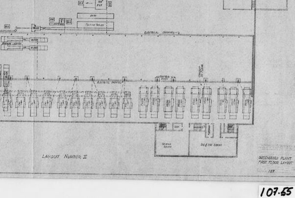
The image is a black and white photocopy of a technical drawing, specifically labeled "LAYOUT Number II" and "GREENSBORO PLANT FIRST FLOOR LAYOUT." It appears to be a floor plan of an industrial or manufacturing plant. The drawing shows various rooms, equipment, and pathways within the plant. There are annotations and labels identifying different areas and machinery.
At the bottom right corner, the drawing is marked with the number "107.55." The overall layout has a rectangular structure with various segmented areas, possibly representing different operational sections of the plant.
Anthropic Claude
Created by claude-3-haiku-20240307 on 2024-12-08
The image appears to be a blueprint or engineering diagram. It shows a detailed layout or schematic, with various components and labels indicated. The diagram is black and white, with fine lines and symbols representing different elements or parts. The layout is labeled "Layout Number II", suggesting this is part of a larger set of plans or schematics. The image provides a technical, engineering-focused view of some kind of system or structure.
Created by claude-3-5-sonnet-20241022 on 2024-12-08
This appears to be an architectural floor plan or layout drawing, labeled as "LAYOUT NUMBER II." The image shows what seems to be an industrial or manufacturing facility layout with various rectangles and boxes representing different areas or equipment. Along one side, there appears to be a row of regularly spaced rectangular units, possibly representing workstations or machinery. In the bottom right corner, there are two smaller rooms labeled, though the text is difficult to read clearly in this black and white document. The drawing has a number "107-65" marked on it, likely a reference or drawing number. The image is presented in a framed or mounted format with a dark border around it.
Created by us.anthropic.claude-3-5-sonnet-20241022-v2:0 on 2025-06-26
This appears to be an architectural or engineering floor plan drawing labeled "LAYOUT NUMBER II." The drawing shows what seems to be an industrial or manufacturing facility layout with various rectangular sections and spaces marked out. Along one side there appears to be a row of uniformly-sized rectangular spaces, possibly representing work stations or equipment locations. There are also some smaller rooms or areas labeled in the corner of the plan. The drawing is presented in a simple line-drawing style typical of architectural blueprints, and appears to be an older document based on its style and the black and white presentation. The number "107-65" is visible in the corner of the frame.
Meta Llama
Created by us.meta.llama3-2-11b-instruct-v1:0 on 2024-12-08
The image presents a black-and-white floor plan of a building, showcasing its layout and various rooms. The plan is drawn on a piece of paper, which appears to be slightly wrinkled, and is surrounded by a black border. The floor plan is labeled "LAYOUT NUMBER II" in the bottom-left corner, indicating that it is a second version of the layout.
Key Features:
- Layout: The floor plan features a rectangular shape with several rooms and corridors.
- Rooms: The rooms are represented by rectangles of varying sizes, with some featuring labels such as "Office", "Laboratory", and "Storage".
- Corridors: The corridors are depicted as narrow rectangles connecting the rooms.
- Labels: The plan includes labels for various rooms and features, such as "Office", "Laboratory", "Storage", and "Water Closet".
- Border: The floor plan is surrounded by a black border, which adds a touch of elegance to the overall design.
- Background: The background of the image is a light gray color, which provides a clean and neutral backdrop for the floor plan.
Overall:
The image presents a clear and detailed floor plan of a building, showcasing its layout and various rooms. The use of labels and a black border adds a touch of professionalism to the design, making it suitable for architectural or engineering purposes.
Created by us.meta.llama3-2-90b-instruct-v1:0 on 2024-12-08
This image is a black and white architectural blueprint of a building's floor plan, specifically the first floor. The blueprint is labeled "Layout Number II" and features a rectangular shape with various rooms and spaces marked throughout. The rooms are represented by rectangles of different sizes, with some containing additional details such as doorways, windows, and labels indicating their purpose.
In the bottom-right corner of the blueprint, there is a small box containing the text "Springfield Plant First Floor Layout" and the number "107." Below this, another box contains the number "107.65." The background of the blueprint is a light gray color, providing a clean and neutral backdrop for the architectural details.
Overall, this image provides a detailed and informative view of the building's layout, allowing viewers to visualize the space and understand its various components.
Amazon Nova
Created by amazon.nova-lite-v1:0 on 2025-02-28
The image is a floor plan for a facility, specifically the "Greenhouse Plant First Floor Layout." The layout number is "107-55," and it's dated "107.55." The floor plan is divided into sections, with the upper section labeled "LAYOUT NUMBER II." There are various symbols and annotations on the floor plan, likely representing different equipment, machinery, or areas within the facility. The floor plan is surrounded by a black border, and the entire image has a slightly blurred effect, possibly due to age or quality of the original document.
Created by amazon.nova-pro-v1:0 on 2025-02-28
The image shows a floor layout of a plant, with the number "107-55" written on the bottom right corner. The layout is divided into several sections, each labeled with a number. The sections are arranged in a grid-like pattern, with some sections overlapping. The layout appears to be a top-down view of the plant, with the different sections representing different areas or departments within the plant. The image is in black and white, and the layout is drawn on a piece of paper with a ruler. The image appears to be a technical drawing or blueprint of the plant's floor layout.
Google Gemini
Created by gemini-2.0-flash-lite on 2025-05-18
Here is a description of the image:
The image shows a black and white architectural blueprint or technical drawing, likely a floor plan. The drawing is enclosed within a black frame, giving the impression that it is a mounted photograph or print.
The blueprint depicts what appears to be a factory or industrial plant layout. It's labeled as "Greenhouse Plant, First Floor Layout." The plan includes various rectangular shapes that may represent rooms or equipment. It shows detailed sections with elements like machines, storage areas, and perhaps administrative spaces. There are labeled areas such as "Dye & Ink Room", "Electrical Channels," and "Maintenance Room."
The image has a crisp and clear quality to it, suggesting a high-resolution scan or photograph of the original document. There are indications of age and the physical condition of the drawing, with some imperfections visible, adding a certain charm.
At the bottom of the image are the words "Layout Number II" and "107.65," which are most likely references to the project or plan number.
Created by gemini-2.0-flash on 2025-05-18
Here is a description of the image:
The image shows a black and white architectural drawing titled "Greensboro Plant First Floor Layout." The drawing is labeled "Layout Number II" and numbered "107.65." It appears to be a layout of a factory or industrial space, featuring various room configurations, equipment, and pathways, including areas marked "Electrical Channels" and "Off Inc Room." The drawing is framed and has a slight crease or fold along the right edge.
Mistral Pixtral
Created by us.mistral.pixtral-large-2502-v1:0 on 2025-06-03
The image depicts a framed architectural floor plan, labeled "Layout Number II." It appears to be a detailed blueprint for a processing plant, specifically the "first floor layout," as indicated in the bottom right corner of the drawing. The plan includes various labeled sections and areas, such as "Raw Water," "Sewage," "Office Space," and "Main Pump Room." The layout shows the spatial arrangement of these sections within the building.
Key elements visible in the blueprint include:
- A series of rectangular structures or rooms aligned in rows, possibly indicating machinery or processing units.
- Specific areas designated for different functions, such as water treatment and sewage processing.
- An office space and a main pump room, suggesting administrative and operational areas within the plant.
- Detailed annotations and measurements, providing precise dimensions and spatial relationships between different parts of the layout.
The drawing is dated "197" in the bottom right corner, suggesting it was created in the year 1970 or later. The number "109.65" is written on a label attached to the bottom right of the frame, which might be a reference or catalog number for the blueprint.
Qwen
Created by Qwen/Qwen2.5-VL-7B-Instruct on 2025-07-27
The image appears to be a technical drawing or blueprint, specifically labeled as "Layout Number II." It seems to be a floor plan for a Greenwood Plant, as indicated by the text in the bottom right corner. The drawing is oriented in a landscape format and includes various labeled areas and components.
The layout includes several rectangular sections that likely represent different rooms or functional areas within the plant. There are also lines and annotations that suggest the placement of machines, equipment, or pathways, along with labels for electrical channels and ventilation shafts.
The diagram is detailed, with precise measurements and labels for each component, making it appear to be a professional architectural or engineering drawing. The numbers "107-55" at the bottom right corner might be a reference or identifier for the drawing. The black border and the white background enhance the clarity and focus on the technical details of the plan.
Created by Qwen/Qwen2.5-VL-72B-Instruct on 2025-07-27
This image shows a technical architectural floor plan labeled "Layout Number II." It appears to be a detailed diagram of a greenhouse plant's first-floor layout. The layout features a long rectangular structure with rows of evenly spaced sections, likely representing growing areas or benches for plants. There are various labeled sections that could indicate different functional areas within the greenhouse, such as mechanical rooms, electrical channels, and storage areas. The diagram includes annotations and numbers, possibly indicating dimensions or other specifications. The image is black and white and has a label "107-55" in the bottom right corner.
Text analysis
Amazon