
Machine Generated Data
Tags
Color Analysis
Feature analysis
Amazon
Clarifai
AWS Rekognition
| Monitor | 62.4% | |

Categories
Imagga
created on 2022-06-04
| text visuals | 99.9% | |
Captions
Microsoft
created by unknown on 2022-06-04
| a screen shot of a glass door | 56.5% | |
| a screen shot of an open door | 56.4% | |
| a close up of a glass door | 56.3% | |
Clarifai
No captions written
Salesforce
Created by general-english-image-caption-blip on 2025-05-21
a photograph of a drawing of a plan for a boat
Created by general-english-image-caption-blip-2 on 2025-06-29
a black and white photo of a chart with lines and graphs
OpenAI GPT
Created by gpt-4 on 2024-12-07
This image displays a black and white photograph of a framed architectural drawing or engineering plan. The drawing has multiple horizontal sections, each representing a different cross-section of what appears to be a ship or boat hull design. You can see various lines and shapes that indicate the contours of the hull at different points along its length. There are labels such as "Water Line" and "Section" followed by numbers, suggesting that each section corresponds to a particular level or aspect of the design.
In the lower right corner of the frame, there is a label or plaque with text that is partly legible, indicating specifics related to the draft, depth of hold, and other characteristics. There's also a number "106.51," which might be an identification or cataloging number for the document or photograph.
The photograph itself shows signs of age with some discolorations or foxing on the paper. The overall impression is that this image represents a technical document from naval architecture or marine engineering and is likely historical in nature.
Created by gpt-4o-2024-05-13 on 2024-12-07
The image is a black and white photograph of a framed technical drawing. The drawing appears to be engineering or architectural plans, featuring multiple line graphs and diagrams along with numerical markings.
The title block in the bottom right corner reads:
“SCHUYLKILL NAVIGATION COMPANY:
Plan Showing Cross Sections of Proposed Canal
Routing Project No. 2, Reading to Philadelphia, PA
Scale 1” = 100’”
Sections are labeled numerically from 1 through 8. Each section is a detailed representation likely showing dimensions, elevations, and design details for segments of the canal. There are labels, numerical notations, and hatchings to indicate different areas or materials.
Additionally, there is a small plaque below the title block with text indicating the drafter's initials and other details, some of which are not fully legible in this image. The bottom right corner is numbered "106.51".
The frame around the drawing suggests it is preserved for display or archival purposes.
Anthropic Claude
Created by us.anthropic.claude-3-5-sonnet-20241022-v2:0 on 2025-06-25
This image appears to be an engineering or architectural drawing showing multiple cross-sectional views of what seems to be a canal or navigation system. The drawing consists of 8 different horizontal sections labeled "Section 1" through "Section 8". Each section shows elevation profiles with various gradients and features. The drawings are technical in nature, showing detailed measurements and engineering specifications. Some sections include shaded areas that might represent earthworks or structural elements. The document appears to be a historical technical drawing, possibly from a navigation company's plans for water infrastructure. The image is in black and white and appears to be a photograph or scan of an original engineering document.
Created by claude-3-haiku-20240307 on 2024-12-07
This image appears to be an engineering diagram or technical drawing. It contains multiple cross-sectional views or profiles of some kind of structure or object, with detailed measurements and labels. The diagrams appear to be part of a larger "Columbia Navigation Surveys" document or project, as indicated by the title at the bottom of the image. The overall impression is of a technical, engineering-focused image rather than a photograph or artistic work.
Created by claude-3-5-sonnet-20241022 on 2024-12-07
This appears to be an engineering or architectural drawing showing multiple cross-sectional views of what looks like a canal or navigation system. The image contains eight different horizontal sections labeled from 1 through 8, each showing elevation profiles with various gradients and structural elements. The drawings are technical in nature, with measurement markings and scale indicators along the sections. The document appears to be from the Pennsylvania Navigation Company, based on text visible in the corner. It's a black and white technical document, likely a historical engineering plan, possibly for canal construction or modification. Each section shows slightly different topographical features and structural elements, with some areas shaded to indicate different elevations or construction zones.
Meta Llama
Created by us.meta.llama3-2-11b-instruct-v1:0 on 2024-12-07
The image presents a technical drawing of a naval navigation canal, showcasing various sections with detailed measurements and annotations. The drawing is rendered in black and white, with a clear and organized layout that facilitates understanding.
Key Features:
- Title: "BENUEHILL NAVIGATION CANAL" is inscribed in the bottom-right corner, providing context for the drawing.
- Sectional Breakdown: The drawing is divided into multiple sections, each labeled and featuring distinct measurements and annotations.
- Measurements: Various measurements are provided throughout the drawing, including dimensions, angles, and distances.
- Annotations: Small notes and labels are scattered throughout the drawing, offering additional information and clarification on specific aspects of the canal's design.
- Scale: A scale is present in the bottom-right corner, indicating the proportionality of the drawing to the actual canal.
- Background: The background of the drawing is a light gray color, providing a clean and neutral backdrop for the technical information.
Overall Impression:
The image conveys a sense of precision and attention to detail, suggesting that the drawing is a critical component of the canal's design and construction process. The use of clear labels, measurements, and annotations ensures that the drawing is easily understandable by those familiar with naval navigation canals.
Created by us.meta.llama3-2-90b-instruct-v1:0 on 2024-12-07
The image depicts a black-and-white document featuring a series of graphs and charts, likely related to navigation or engineering. The document is presented in a black frame with a white background, and it appears to be an old or vintage item.
Key Features:
- Graphs and Charts: The document contains multiple graphs and charts, which are arranged in a grid-like pattern. These visual aids are used to represent data and trends, but the specific details are not immediately clear.
- Navigation or Engineering Context: The presence of graphs and charts suggests that the document is related to navigation or engineering. This could include topics such as water levels, navigation channels, or structural designs.
- Vintage Appearance: The document has a vintage appearance, with visible signs of aging and wear. This suggests that it may be an older item, possibly from the early 20th century or earlier.
- Black Frame and White Background: The document is presented in a black frame with a white background, which helps to highlight the contents and create a sense of contrast.
Conclusion:
In conclusion, the image depicts a vintage document featuring graphs and charts related to navigation or engineering. The document's age and condition suggest that it may be a historical artifact, and its contents could provide valuable insights into the field of navigation or engineering during a specific time period.
Amazon Nova
Created by amazon.nova-lite-v1:0 on 2025-02-26
This image appears to be a technical drawing or diagram of a canal or waterway. The image shows a series of sections or cross-sections of the canal, with different labels and measurements indicating various features of the waterway.
The top section of the image shows a water line, which likely represents the normal water level in the canal. Below this, there are several sections labeled "Section 1," "Section 2," and so on, each with its own set of measurements and labels.
The labels and measurements on the sections include terms such as "high water line," "water line," "section," and "section 2." These likely indicate different features of the canal, such as the maximum water level, the normal water level, and the dimensions of the canal itself.
At the bottom of the image, there is a label that reads "SCHUYLKILL NAVIGATION COMPANY." This likely indicates the name of the company or organization responsible for maintaining or operating the canal.
Overall, the image appears to be a technical diagram or plan of a canal or waterway, showing various sections and measurements to provide information about the dimensions and features of the waterway.
Created by amazon.nova-pro-v1:0 on 2025-02-26
The image shows a plan showing the cross-section of a canal opposite the plant of the Philadelphia Paper Manufacturers Company. The image is in black and white, and it appears to be a technical drawing or blueprint. The image is divided into several sections, each labeled with a number. The sections show the different layers of the canal, including the water line, the section, and the material. The image also includes a title and a reference number, which suggests that it is part of a larger set of plans or drawings.
Google Gemini
Created by gemini-2.0-flash on 2025-05-18
Here's a description of the image:
General Description:
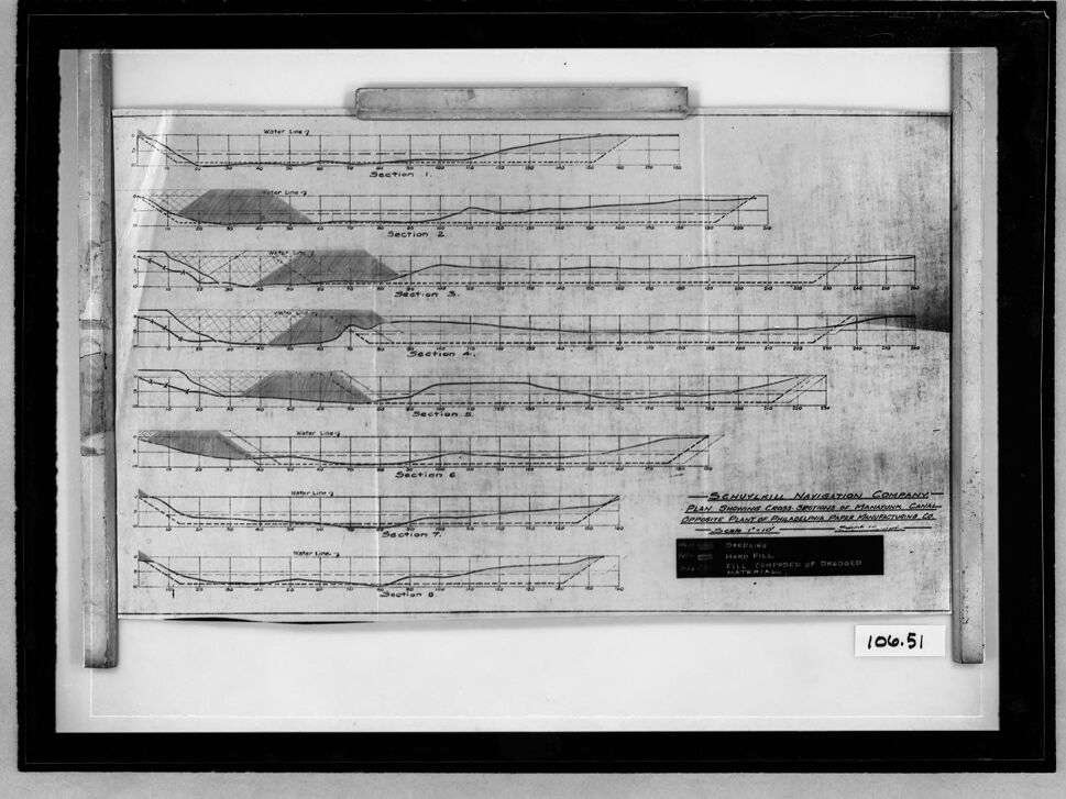
The image is a black and white photograph of a framed technical drawing or plan. The drawing is titled "SCHUYLKILL NAVIGATION COMPANY - PLAN SHOWING CROSS SECTIONS OF MANAYUNK CANAL OPPOSITE PLANT OF PHILADELPHIA PAPER MANUFACTURING CO." A section of the image has a handwritten number "106.51".
Drawing Details:
The drawing displays a series of eight cross-sectional diagrams, labeled "Section 1" through "Section 8". Each section shows a topographical profile, with horizontal grid lines and numerical scales. Water lines are indicated, and areas are shaded to represent different materials, as indicated by a legend: "GARDENING", "HARD FILL" and "FILL, COMPOSED OF DREDGED MATERIAL".
Created by gemini-2.0-flash-lite on 2025-05-18
The image is a black and white photograph of a framed technical drawing or plan. The plan appears to be a set of cross-sectional diagrams, likely related to the construction or analysis of a waterway or channel.
Here's a breakdown of the details:
- Content: The main focus is on the set of cross-sectional diagrams. There are eight sections labeled from "Section 1" to "Section 8," each depicting a profile with horizontal and vertical axes. Lines and shaded areas within the diagrams likely represent the depth, shape, and composition of the waterway at various points. "Water Line 3" is labeled in each section.
- Title/Information: A title block or text at the bottom of the plan reads "SCHUYLKILL NAVIGATION COMPANY," the "PLAN SHOWING CROSS SECTIONS OF MANAYUNK CANAL OPPOSITE PLANT OF PHILADELPHIA PAPER MANUFACTURING CO" and provides a scale of 1'10'.
- Framing: The artwork is enclosed within a black frame.
- Condition: The photograph itself seems to be somewhat aged or perhaps a reproduction of an older document, given the slight imperfections and texture of the paper. The number "106.51" is written at the bottom right.
Overall, the image appears to be a historical document related to engineering, surveying, or construction, specifically focusing on a navigation project.
Mistral Pixtral
Created by us.mistral.pixtral-large-2502-v1:0 on 2025-06-06
The image depicts a detailed technical drawing or blueprint, likely related to maritime or naval engineering. The drawing is encased in a frame, and the paper appears aged, suggesting it is an old document. The content of the drawing includes several cross-sectional views labeled as "Section 1" through "Section 8," each showing the profile of a ship's hull at different points along its length.
Key features of the drawing include:
- Cross-Sections: Each section shows the shape and dimensions of the ship's hull at various points, indicating the contours and structural details.
- Water Lines: There are water lines marked on the drawing, which likely represent the waterline of the ship at different load conditions.
- Measurements: The drawing includes various measurements and annotations, providing specific dimensions and details about the hull's structure.
- Labels and Annotations: The drawing includes labels such as "Water Line 1," "Water Line 2," and "Section 1" through "Section 8." There is also a title block in the lower right corner with text that reads "Skinner & Eddy Corporation, Plan, Bonhomme, Richard Class Sections at Designated Stations, Scale 3/8" = 1'-0," and additional details about the drawing number and date.
- Draught Information: There is a note indicating the draught (depth of the ship's hull below the waterline) for different conditions.
Overall, the image is a detailed and precise engineering document used for the design and construction of a ship, providing critical information about the hull's shape and dimensions at various points.
Qwen
No captions written
Text analysis
Amazon


