Machine Generated Data
Tags
Color Analysis
Feature analysis
Amazon
Clarifai
AWS Rekognition
| Rug | 81.3% | |

Categories
Imagga
created on 2022-06-04
| text visuals | 99.9% | |
Captions
Microsoft
created by unknown on 2022-06-04
| a room with art on the wall | 68.1% | |
| a close up of text in a room | 68% | |
| a close up of text on a white surface | 57.6% | |
Clarifai
No captions written
Salesforce
Created by general-english-image-caption-blip on 2025-05-18
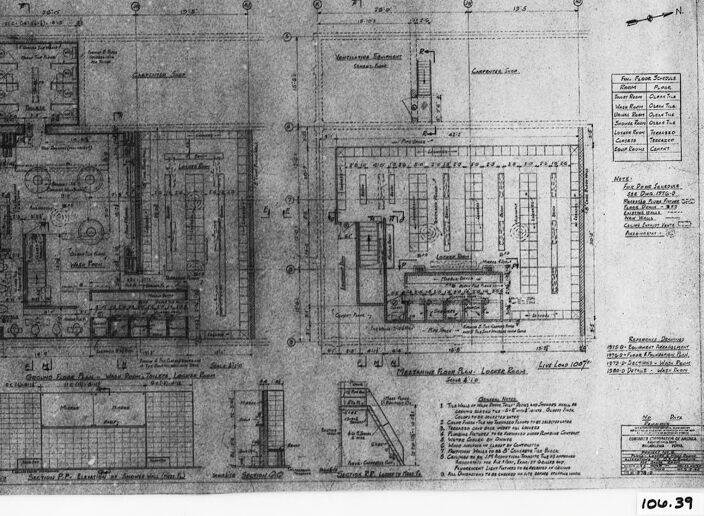
a photograph of a drawing of a plan for a building
Created by general-english-image-caption-blip-2 on 2025-06-28
a black and white drawing of a building with plans
OpenAI GPT
Created by gpt-4 on 2024-12-07
The image shows a black-and-white architectural drawing or blueprint of a building. The drawing includes floor plans with labeled rooms and sections. There are detailed dimensions marked on the various parts of the structure, indicating the precise sizes for construction. On the right side of the image, there are notes and a key to the types of lines used within the drawing, such as those for brick, stone, or plaster. Also, detailed cross-section views of parts of the building are visible, which are typically used to provide a more in-depth understanding of vertical relationships within a structure. The entirety of the drawing is bordered by a black frame, and there is a marking "100.39" in the bottom right corner of the frame.
Created by gpt-4o-2024-05-13 on 2024-12-07
The image displays a technical architectural blueprint or drawing. This detailed plan appears to show floor plans and cross-sectional views of a building. The drawing includes a grid system with multiple measurements and annotations, technical symbols, and labels. Several sections of the blueprint outline different areas and equipment arrangements within the structure, such as rooms and possible mechanical elements. The document is enclosed in a black frame and has a reference number "106.39" at the bottom right corner. There are various textual notes and possibly a north directional arrow, indicating the orientation of the blueprint.
Anthropic Claude
Created by us.anthropic.claude-3-5-sonnet-20241022-v2:0 on 2025-06-24
This appears to be an architectural blueprint or technical drawing. It shows various floor plans, sections, and details of what seems to be a building or facility layout. The drawing includes multiple views including what appears to be a main floor plan on the left side and additional detailed sections and elevations around it. The document contains measurements, annotations, and technical notes typical of architectural drawings. The image is in black and white, appearing to be a photographic reproduction of the original drawing. There's a reference number "100.39" visible in the bottom right corner. The drawing appears to be quite detailed with careful attention to spatial relationships and building specifications.
Created by claude-3-haiku-20240307 on 2024-12-07
The image appears to be a detailed architectural blueprint or engineering drawing. It contains various technical diagrams, schematics, and annotations related to the layout and design of a building or structure. The drawing includes floor plans, elevations, and other technical specifications. Overall, the image seems to be a comprehensive technical document intended for the construction or planning of a specific building or facility.
Created by claude-3-5-sonnet-20241022 on 2024-12-07
This appears to be an architectural or technical drawing/blueprint, shown in black and white. The image shows various floor plans, elevations, and detailed sections of what appears to be some kind of industrial or institutional building. There are multiple views including what looks like a main floor plan on the left side, with smaller supplementary drawings and details around it. The drawing includes measurements, annotations, and technical notes. The document appears to be historical, given its aged appearance and traditional drafting style. There are grid patterns and measurement scales visible in some sections of the drawing, and the overall layout suggests this is a professional architectural or engineering document.
Meta Llama
Created by us.meta.llama3-2-11b-instruct-v1:0 on 2024-12-07
The image presents a detailed architectural blueprint, showcasing the floor plan of a building. The blueprint is rendered in black and white, with various sections and labels indicating different areas of the structure.
- Floor Plan
- The floor plan is divided into several sections, each representing a distinct area of the building.
- The sections are labeled with letters and numbers, providing a clear understanding of the layout.
- The blueprint includes measurements and dimensions for each section, allowing for precise construction and design.
- Labels and Notations
- Throughout the blueprint, various labels and notations are present, providing additional information about the building's design and features.
- These labels include room names, door and window locations, and other important details.
- The notations also include symbols and abbreviations, which are likely specific to the architect or designer who created the blueprint.
- Dimensions and Measurements
- The blueprint includes precise dimensions and measurements for each section of the building.
- These measurements are essential for ensuring that the building is constructed accurately and to scale.
- The dimensions are often accompanied by arrows or other indicators, highlighting the direction and orientation of the building's features.
- Architectural Features
- The blueprint showcases various architectural features, such as columns, arches, and other decorative elements.
- These features are carefully designed and proportioned to create a visually appealing and functional building.
- The blueprint also includes details about the building's materials and construction methods, providing a comprehensive understanding of the structure's design and execution.
In summary, the image presents a detailed and informative architectural blueprint, providing a clear understanding of the building's design, layout, and features. The blueprint is meticulously drawn, with precise measurements and labels, making it an essential tool for architects, builders, and designers.
Created by us.meta.llama3-2-90b-instruct-v1:0 on 2024-12-07
The image depicts a black-and-white architectural drawing of a building's floor plan, presented in a landscape orientation. The drawing is set against a white background and features a black border around it.
Key Features:
- Floor Plan: The floor plan is the central element of the image, showcasing the layout of the building's interior spaces.
- Black Border: A black border surrounds the floor plan, adding a touch of contrast to the overall design.
- White Background: The white background provides a clean and neutral backdrop for the floor plan, allowing the viewer to focus on the architectural details.
Additional Elements:
- Handwritten Notes: Scattered throughout the floor plan are handwritten notes, likely providing additional information about the building's design and features.
- Scale: A scale is visible in the bottom-right corner of the image, indicating the proportion of the drawing to the actual building.
Overall Impression:
The image presents a detailed and informative architectural drawing, showcasing the building's floor plan and various features. The use of a black border and white background creates a visually appealing contrast, while the handwritten notes and scale add an extra layer of depth to the image.
Amazon Nova
Created by amazon.nova-lite-v1:0 on 2025-02-28
The image is a black-and-white architectural blueprint of a building floor plan. It shows a detailed layout of the space, including dimensions and annotations. The floor plan is divided into sections, each labeled with a unique identifier. The blueprint includes various elements such as doors, windows, walls, and structural supports. The dimensions are provided in both feet and inches, and there are notes and annotations throughout the plan, likely indicating specific design considerations or construction details. The image appears to be a professional architectural drawing, possibly used for construction or renovation purposes.
Created by amazon.nova-pro-v1:0 on 2025-02-28
The image depicts a detailed architectural blueprint, likely for a residential or commercial building. The blueprint is divided into several sections, each containing specific information about the building's layout and design. The top section of the blueprint shows the floor plan, with various rooms and spaces labeled, including bedrooms, bathrooms, living areas, and kitchens. The bottom section of the blueprint contains additional information, such as dimensions, materials, and construction details. The blueprint also includes a legend, which explains the symbols and abbreviations used throughout the document. Overall, the blueprint provides a comprehensive overview of the building's design and construction, allowing architects, engineers, and contractors to accurately plan and execute the project.
Google Gemini
Created by gemini-2.0-flash-lite on 2025-05-18
Here's a description of the image:
Overall:
The image is a framed architectural or engineering drawing, likely a blueprint or a plan. It appears to be an industrial or commercial layout due to the detailed depictions of machinery, rooms, and structures. The drawing is in black and white, showing a detailed layout of rooms and equipment.
Specific Details:
- Format: The drawing is on a sheet of paper, framed.
- Layout: It features a complex arrangement of lines, shapes, and notations, characteristic of technical drawings.
- Content: The drawing includes:
- Multiple interconnected areas with labels like "Waste Pool", "Ventilation Equipment," "Locker Room", "Locker Room," and "Live Load".
- Equipment and machinery symbols, representing various functional elements within the building or facility.
- Gridlines and dimensions, used for scaling and spatial referencing.
- Text labels and notations, providing information about specific areas, components, and dimensions.
- A compass rose indicating the north direction.
- Context: This is a historical document, as the image appears aged.
If you'd like, give me another image to describe!
Created by gemini-2.0-flash on 2025-05-18
Here is a description of the image:
The image is a black and white photograph of a framed technical drawing or blueprint. The drawing is complex, filled with lines, labels, and geometric shapes, suggesting a floor plan or engineering schematic.
The drawing is divided into multiple sections, each depicting a different view or aspect of the same structure. Text and tables are present, providing details about dimensions, materials, and other specifications. The overall impression is that it's a detailed, technical document created for construction or engineering purposes.
The frame around the drawing is black, adding a sense of formality and importance to the document. The photograph itself is slightly grainy, adding a vintage feel to the image.
Mistral Pixtral
Created by us.mistral.pixtral-large-2502-v1:0 on 2025-06-06
The image shows a detailed architectural blueprint or floor plan of a building, likely a commercial or industrial structure. The blueprint includes several sections, each labeled with specific room names and dimensions. Here is a detailed summary of the visible sections and features:
Main Sections:
- Ventilating and Heating Chamber Room: This section appears to be dedicated to the building's HVAC (Heating, Ventilation, and Air Conditioning) systems.
- Caretaker's Room: This room is likely designated for the building's maintenance personnel.
- Lighting Room: This area is presumably for electrical and lighting controls.
- Engine Room: This section is for housing machinery or engines.
- Boiler Room: This area is designated for the building's boilers, which are essential for heating.
- Coal Room: This room is for storing coal, which would be used to fuel the boilers.
- Ash Room: This area is for collecting and storing ash produced by the boilers.
- Pump Room: This room is for housing pumps, likely related to the building's water or heating systems.
- Toilet Room: This is a restroom area.
- Staircases and Elevators: The blueprint shows the locations of staircases and elevators for vertical movement within the building.
Dimensions and Measurements:
- The blueprint includes precise measurements for each room and section, providing detailed dimensions for construction purposes.
- The measurements are given in feet and inches, indicating the size and layout of each area.
Annotations and Notes:
- The blueprint includes various annotations and notes, providing additional details about the structure and its components.
- There are sections labeled with specific instructions or descriptions, such as "Trench under Boiler Room" and "Coal Conveyor."
Sections and Elevations:
- The blueprint includes cross-sectional views and elevations, showing the vertical layout of the building and the relationship between different floors.
- These sections provide detailed information about the structural elements and the arrangement of rooms on different levels.
Legend and Symbols:
- The blueprint includes a legend or key, explaining the symbols and abbreviations used in the drawing.
- This helps in understanding the various components and features depicted in the blueprint.
Overall, the image provides a comprehensive and detailed plan of a building's lower levels, focusing on mechanical and utility rooms essential for the building's operation.
Qwen
No captions written
Text analysis
Amazon