Machine Generated Data
Tags
Color Analysis
Feature analysis
Amazon
Clarifai

Clarifai
| Picture frame | 99.5% | |
Categories
Imagga
created on 2022-06-04
| text visuals | 99.9% | |
Captions
Microsoft
created by unknown on 2022-06-04
| a close up of a sign | 72% | |
| a sign on a wall | 62.2% | |
| a close up of text on a screen | 46.7% | |
Clarifai
No captions written
Salesforce
Created by general-english-image-caption-blip on 2025-05-05
a photograph of a black and white photo of a house plan
Created by general-english-image-caption-blip-2 on 2025-07-02
a drawing of a house with plans and drawings
OpenAI GPT
Created by gpt-4 on 2024-12-07
The image displays a framed architectural drawing or blueprint. It consists of several detailed sections and elevation views of a building's construction. The various parts of the structure, like doors, windows, and rooms, are labeled with dimensions and notes. These labels indicate the specific materials and construction techniques to be used. The layout allows a builder or architect to understand the design from different perspectives, such as front, side, and cross-sectional views. Overall, it appears to be a professional document used for constructing or renovating a building, with annotations suggesting it might be of a significant age, given the style of the drawings and markings.
The image quality is not crystal clear, with visible signs of wear and age, such as creases and faded sections. This gives the impression of an older document, possibly historical. The edges of the drawing are a bit tattered, indicating it has been handled or displayed over time. The drawing is shown within a black frame, enhancing its presentation and suggesting it might be on display or preserved for its importance or historical value. The number "100-38" is visible at the bottom right, which could be a reference or catalog number used for archiving or inventory purposes.
Created by gpt-4o-2024-05-13 on 2024-12-07
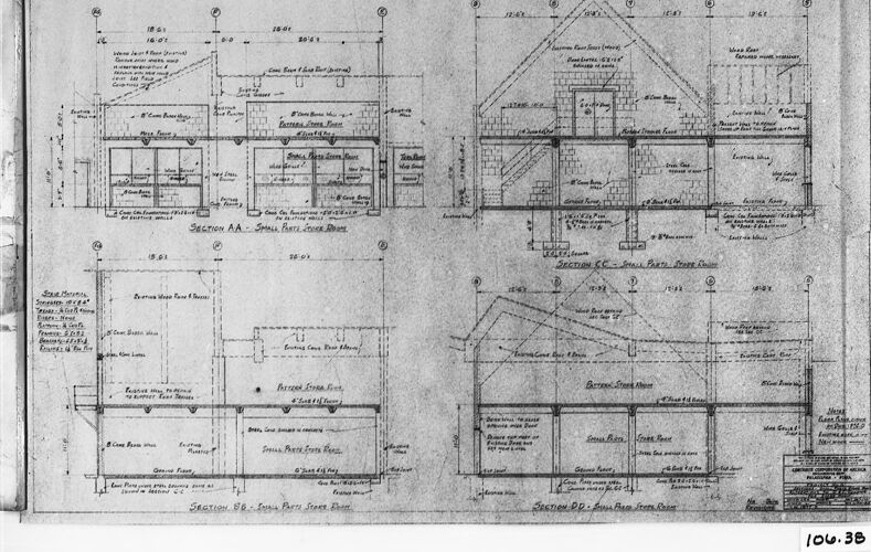
The image shows a detailed architectural blueprint or technical drawing. The drawing features various sections and elevations of a building structure, presented with precise measurements and annotations. The blueprint includes multiple cross-sections labeled as Section A-A, Section B-B, Section C-C, and Section D-D, illustrating different parts and views of the interior and exterior of the building.
The annotations detail specific materials, dimensions, and construction techniques, and the drawing includes notes on walls, floors, rooms, and other structural elements. The image is framed and has a label or reference number "106.38" written in the bottom right corner.
Anthropic Claude
Created by us.anthropic.claude-3-5-sonnet-20241022-v2:0 on 2025-06-25
This image shows architectural blueprints or technical drawings of what appears to be a residential building. The drawings include multiple cross-sectional views (labeled as "Section AA" and "Section BB") showing the internal layout and structure of the building. The plans display detailed measurements, room labels, and construction notes. The drawings show both vertical and horizontal sections of what looks like a two-story house with various rooms and a pitched roof. The blueprint is done in a traditional architectural drawing style with clean lines and precise dimensions marked throughout. It appears to be a historical document, given the black and white format and traditional drafting techniques used.
Created by claude-3-haiku-20240307 on 2024-12-07
This image appears to be an architectural or engineering blueprint or technical drawing. It contains detailed plans, measurements, and annotations detailing the layout and specifications of a structure or building. The drawing includes multiple views, cross-sections, and dimensions, suggesting it is a comprehensive set of plans for constructing or designing a complex structure. Without identifying any individuals, the image seems to be a technical document used in the planning and construction of a building or facility.
Created by claude-3-5-sonnet-20241022 on 2024-12-07
This image appears to be an architectural blueprint or technical drawing showing various cross-sectional views of a house or building. The drawing includes multiple sections labeled as "Section AA" and "Section BB," showing the interior layout and structural details from different angles. The plans show both vertical and horizontal cross-sections of what appears to be a two-story structure with a pitched roof. The drawings are quite detailed, including measurements, annotations, and various architectural elements such as walls, floors, and roof lines. The document is presented in a traditional architectural drawing style with black lines on a white background, and it appears to be a historical or vintage document based on its style and presentation.
Meta Llama
Created by us.meta.llama3-2-11b-instruct-v1:0 on 2024-12-07
The image presents a black-and-white architectural drawing of a house, showcasing its floor plan and elevations. The drawing is rendered in pencil and features various measurements and labels.
Key Features:
- Floor Plan: The floor plan is divided into sections, each labeled with a letter (AA, BB, CC, etc.). These sections provide detailed information about the layout of the house, including room sizes, door and window locations, and other architectural features.
- Elevations: The elevations of the house are also depicted, offering a three-dimensional view of the building's exterior. This allows for a better understanding of the house's design and construction.
- Measurements: Throughout the drawing, measurements are provided in both feet and inches, ensuring accuracy and precision in the design and construction process.
- Labels: Various labels are used to identify different components of the house, such as doors, windows, and rooms. These labels help to clarify the layout and functionality of the space.
- Pencil Drawing: The drawing is created using pencil, which provides a clear and detailed representation of the house's design. The pencil lines are smooth and well-defined, making it easy to read and interpret the information presented.
Overall:
The image provides a comprehensive and detailed view of the house's design, making it an essential tool for architects, builders, and homeowners. The use of measurements, labels, and elevations ensures that the design is accurate and functional, while the pencil drawing provides a clear and precise representation of the space.
Created by us.meta.llama3-2-90b-instruct-v1:0 on 2024-12-07
This image presents a detailed architectural drawing of a building, showcasing its layout and design. The drawing is rendered in black ink on white paper, with a black border surrounding it. The building's floor plan is divided into sections, each labeled with letters and numbers, providing a clear understanding of the space.
The drawing includes various symbols and notations, likely indicating specific features or materials used in the construction process. These markings add an extra layer of detail to the design, allowing for a more comprehensive understanding of the building's architecture.
Overall, this image provides a valuable insight into the design and layout of the building, offering a wealth of information for architects, builders, and anyone interested in the construction process.
Amazon Nova
Created by amazon.nova-lite-v1:0 on 2025-02-25
This image is a scanned copy of a technical drawing or blueprint, possibly related to architectural or engineering plans. The drawing appears to be divided into sections, each labeled with a letter (AA, BB, CC, DD) and a corresponding number (106.38). The sections are further divided into smaller subsections, with dimensions and measurements indicated in various places.
The drawing features a mix of text, numbers, and lines, suggesting it is a detailed plan or blueprint. The text includes abbreviations and technical terms, which are likely specific to the field of architecture or engineering. The lines and measurements indicate the dimensions of various components, such as walls, doors, and windows.
The image is monochromatic, with a black border around the edges, which is common for technical drawings and blueprints. The drawing appears to be an older document, possibly from the mid-20th century, based on the style and format of the drawing.
Overall, the image is a technical drawing or blueprint that provides detailed information about the design and construction of a building or structure. The drawing is divided into sections and subsections, with dimensions and measurements indicated throughout, making it a valuable resource for architects, engineers, and construction professionals.
Created by amazon.nova-pro-v1:0 on 2025-02-25
The image depicts a detailed architectural blueprint of a building, divided into multiple sections. Each section is labeled with a letter (AA, BB, CC, DD) and provides a specific view or perspective of the structure. The blueprint includes measurements, dimensions, and annotations that describe various components of the building, such as walls, floors, and openings. The layout suggests a multi-story building with detailed floor plans and elevations.
Google Gemini
Created by gemini-2.0-flash-lite on 2025-05-06
The image is a blueprint or architectural drawing. It appears to be a technical drawing of a building or structure. The drawing is divided into sections (AA, BB, CC, and DD), each representing a different view or cross-section. The sections seem to detail the layout and construction of a building. There are annotations, labels, and dimensions. The blueprint is contained within a frame, suggesting it has been preserved or framed for display.
Created by gemini-2.0-flash on 2025-05-06
Here is a description of the image:
The image shows a framed technical drawing, likely an architectural plan, presented in black and white. The drawing is divided into four sections labeled "SECTION AA - SMALL PARTE STOCK Дом", "SECTION CCS PARTS," "SECTION BGS PARTS STORE B," and "SECTION DDS Flem Stepe Room." Each section provides detailed cross-sectional views and dimensional information of a structure, indicated by the architectural lines and annotations present. The style and content suggest it could be a blueprint for a building or parts storage facility. A number, "106.38," is visible in the lower right corner of the drawing. The drawing is bordered by a white mat and framed by a black frame, giving it a finished and preserved appearance.
Mistral Pixtral
Created by us.mistral.pixtral-large-2502-v1:0 on 2025-06-03
The image shows a framed architectural blueprint, likely from the early 20th century, depicting cross-sections of a building's design. The blueprint is divided into four sections labeled A-A, B-B, C-C, and D-D, each providing a detailed view of different parts of the structure.
Section A-A (Small Part Store Room):
- This section appears to show a small room, possibly a storage or utility area, with detailed measurements and annotations indicating the placement of walls, doors, and other structural elements.
Section B-B (Store Room from Store):
- This section provides a cross-sectional view of a larger room, possibly a main store room. It includes detailed dimensions and annotations for walls, floors, and structural supports.
Section C-C (Small Part Store Room):
- Similar to Section A-A, this section shows another small room with detailed measurements and annotations for structural elements.
Section D-D (Store Room from Office):
- This section provides a view of a store room from the perspective of an office. It includes detailed dimensions and annotations for walls, floors, and structural supports.
The blueprint includes various annotations and symbols that indicate different materials and structural components, such as concrete floors, brick walls, and steel beams. The measurements are provided in feet and inches, and the blueprint is meticulously detailed, suggesting it was used for precise construction planning.
Overall, the blueprint provides a comprehensive view of the building's internal structure, focusing on the layout and dimensions of various rooms and structural elements.
Qwen
Created by Qwen/Qwen2.5-VL-7B-Instruct on 2025-07-27
The image appears to be a detailed architectural blueprint or drawing, likely for a building or structure. It includes multiple sections labeled with letters (Section AA, Section CC, Section BB, Section DD) and numbers, detailing the construction plans. The drawing is labeled with various elements such as "Small Parts Storage Room," "Larger Part Storage Room," and "Batter Room," indicating the different areas within the structure.
The sections include dimensions, notes, and diagrams that provide a clear understanding of the layout, dimensions, and construction details of each section. The style of the drawing suggests it might be from a mid-20th-century architectural document, given the format and presentation. The blueprint is framed and appears to be a physical copy of the original drawing, as indicated by the visible edges and the slight crease on the left side.
The overall impression is that this is a technical and precise architectural plan, possibly for a commercial or industrial building.
Created by Qwen/Qwen2.5-VL-72B-Instruct on 2025-07-27
This image shows a detailed architectural blueprint or technical drawing of a building, likely from the early-to-mid 20th century. The drawing includes multiple sections and views of the structure, providing both horizontal and vertical perspectives.
Key elements of the blueprint include:
Section A-A: This section appears to show a cross-section of the building, highlighting the roof structure, support beams, and possibly the floor layout. The measurements and labels indicate the dimensions and materials used.
Section B-B: This section provides another cross-sectional view, possibly focusing on a different part of the building. It includes detailed annotations and measurements.
Section C-C: This section shows a more detailed view of the building's structure, including the roof, walls, and possibly the foundation. The annotations and measurements provide specific information about the construction.
Section D-D: This section appears to be a top-down view or a plan view of the building, showing the layout of the rooms and the placement of structural elements.
The blueprint includes various annotations, labels, and measurements, which are essential for the construction and understanding of the building's design. The drawing is detailed and precise, indicating that it was likely created by a professional architect or engineer.
The image is framed, and there is a label in the bottom right corner with the number "106.38," which could be an inventory or reference number for the blueprint.
Text analysis
Amazon