Machine Generated Data
Tags
Color Analysis
Feature analysis
Amazon
Clarifai

Clarifai
| Picture frame | 99.3% | |
Categories
Imagga
created on 2022-06-04
| text visuals | 100% | |
Captions
Microsoft
created by unknown on 2022-06-04
| a screen shot of a computer | 65.1% | |
| a close up of text on a screen | 65% | |
| a screen shot of a computer monitor | 42.3% | |
Clarifai
No captions written
Salesforce
Created by general-english-image-caption-blip on 2025-05-02
a photograph of a black and white photo of a plan of a house
Created by general-english-image-caption-blip-2 on 2025-06-28
a black and white drawing of a building with plans
OpenAI GPT
Created by gpt-4 on 2024-12-07
This image appears to be a photograph of an architectural drawing or blueprint, presented in a black frame. The blueprint shows the layout of a building, including floor plans for different levels or sections. The drawing seems detailed with various labeled rooms, measurements, and possibly structural details.
On the lower part of the blueprint, there is an elevation sketch showing the facade of the building, which gives an idea of its architectural style and window placement. Annotations and dimensions can be seen across the whole document.
In the bottom right corner, there's a box that seems to contain additional information, possibly regarding the blueprint's title, the project details, the architect or engineering firm responsible, the client, or the date of the plan. The drawing is black and white and the text appears to be faded and slightly blurred, making it difficult to read specific details without a higher resolution image.
Created by gpt-4o-2024-05-13 on 2024-12-07
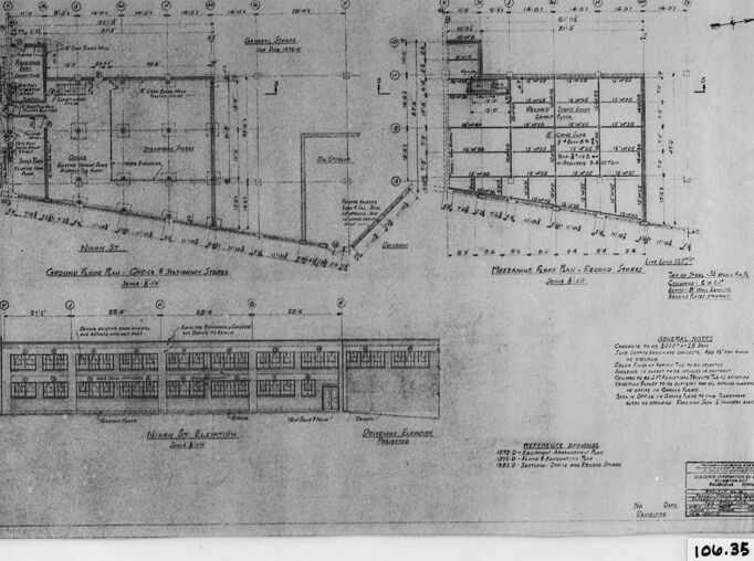
This image is a framed architectural blueprint or technical drawing. The drawing consists of detailed floor plans, including a ground floor plan and mezzanine floor plan for an unnamed structure, with labeled sections and precise measurements. The blueprint shows the layout and structural elements of the building, including rooms, walls, and windows. Additionally, there are notes and annotations possibly related to construction specifications and guidelines. The drawing is inside a frame that provides protection and display for the document, and there is a reference label "106.35" present in the bottom right corner of the frame.
Anthropic Claude
Created by us.anthropic.claude-3-5-sonnet-20241022-v2:0 on 2025-06-24
This image shows an architectural blueprint or technical drawing. It appears to be a building plan that includes floor plans and an elevation view. The drawing is divided into three main sections: two floor plans at the top (possibly ground floor and first floor), and an elevation view at the bottom showing the building's facade. The plans include detailed measurements and room layouts, with various spaces marked out and dimensioned. The drawing is in black and white, typical of architectural blueprints, and includes technical notes and specifications. The document appears to be historical, given its style and presentation, and has been photographed or scanned with a dark border around it. There's also what appears to be a reference number (1016.35) visible in the corner of the image.
Created by claude-3-haiku-20240307 on 2024-12-07
This image appears to be an architectural blueprint or engineering diagram. It shows detailed floor plans and measurements for a multi-story building or complex, with various rooms, spaces, and structural elements labeled and dimensioned. The diagram contains technical drawings, numerical data, and notations that indicate this is a detailed construction or engineering document, likely used for the planning and design of a building or facility.
Created by claude-3-5-sonnet-20241022 on 2024-12-07
This image shows an architectural blueprint or technical drawing. It appears to be a building plan that includes both floor plans and an elevation view. The drawing shows multiple views of what seems to be a commercial or institutional building, with detailed measurements and room layouts. There's a ground floor plan, what appears to be a second floor or basement plan, and a front elevation drawing showing the building's facade. The plans include detailed dimensions and notations typical of architectural drawings. The image is in black and white, and appears to be a historical document or archive copy, given its vintage appearance and the way it's been photographically reproduced.
Meta Llama
Created by us.meta.llama3-2-11b-instruct-v1:0 on 2024-12-07
The image is a black-and-white photograph of a blueprint, which appears to be an architectural drawing or plan for a building. The blueprint is framed in a black frame and has a white border around it.
The blueprint itself is a technical drawing that shows the layout and design of the building, including its dimensions, windows, doors, and other features. It is written in pencil and appears to be hand-drawn. The drawing includes various symbols and notations, such as lines, arrows, and letters, which are used to convey information about the building's design and construction.
In the bottom-right corner of the blueprint, there is a small white label with the number "106.35" written on it in black ink. This label suggests that the blueprint may be part of a larger collection or archive of architectural drawings, and that it has been assigned a unique identifier or catalog number.
Overall, the image provides a detailed and technical view of the building's design and layout, and suggests that it may be an important document for architects, builders, or historians who are interested in the building's history and construction.
Created by us.meta.llama3-2-90b-instruct-v1:0 on 2024-12-07
The image presents a black-and-white architectural blueprint, likely created in the early 20th century, showcasing a building's floor plan and elevation. The blueprint is framed within a black border, with a white background that provides contrast to the detailed drawings.
Key Features:
- Floor Plan: The floor plan occupies the majority of the blueprint, featuring various rooms and spaces labeled with handwritten notes. The plan appears to be a multi-story building, with different levels indicated by distinct sections.
- Elevation: A smaller section of the blueprint displays an elevation view of the building, providing a visual representation of its exterior design. This section is positioned below the floor plan and offers insight into the building's architectural style.
- Handwritten Notes: Throughout the blueprint, handwritten notes are scattered, offering additional information about the building's design and layout. These notes may include measurements, materials, or other relevant details.
- Framing: The blueprint is framed within a black border, which adds a touch of elegance to the overall design. The border also helps to distinguish the blueprint from the surrounding background.
- Background: The background of the image is a plain white, which provides a clean and neutral backdrop for the blueprint. This allows the viewer to focus on the details of the design without distraction.
Conclusion:
In conclusion, the image presents a detailed architectural blueprint that showcases a building's floor plan and elevation. The use of handwritten notes and a black border adds a touch of elegance to the design, while the white background provides a clean and neutral backdrop. Overall, the image offers a fascinating glimpse into the world of architecture and design.
Amazon Nova
Created by amazon.nova-lite-v1:0 on 2025-02-25
The image shows a blueprint or architectural drawing of a building. The drawing is in black and white and appears to be a floor plan or elevation view of a structure. The drawing includes dimensions, labels, and notes indicating various measurements, materials, and other details related to the building's design and construction.
The drawing is divided into sections, with labels such as "Ground Floor Plan," "First Floor Plan," and "Second Floor Plan" indicating the different levels of the building. The drawing also includes notes and measurements related to the building's dimensions, such as "106.35" and "106.35."
The image is framed in a black border, which adds a professional and polished look to the drawing. The drawing appears to be a detailed and technical representation of the building's design, intended for use by architects, engineers, or construction professionals.
Overall, the image provides a glimpse into the design and planning process of a building, showcasing the attention to detail and precision required in architectural and engineering work.
Created by amazon.nova-pro-v1:0 on 2025-02-25
The image shows a black-and-white architectural drawing of a building. The drawing is framed by a black border, and it has a number "106.35" written in the bottom right corner. The drawing includes a floor plan of the building, with various rooms and spaces labeled. The drawing also includes a section of the building, showing the different levels and their heights. The drawing appears to be a detailed and technical representation of the building's design.
Google Gemini
Created by gemini-2.0-flash-lite on 2025-05-01
Here is a description of the image:
The image shows a black and white architectural blueprint framed in a black frame. The blueprint appears to be of a building layout, showing the ground floor and mezzanine floor plans, as well as an elevation view. It includes labels indicating rooms, dimensions, and other architectural details. At the bottom, there's a reference box with the number "106.35" visible. The paper of the blueprint has a yellowed, aged appearance.
Created by gemini-2.0-flash on 2025-05-01
Here's a description of the image:
The image is a black and white photograph of a framed technical drawing, possibly an architectural plan or blueprint. The drawing itself contains several different views of what appears to be a building or structure.
The main elements of the drawing include:
- Floor Plans: There are at least two distinct floor plan layouts, one labeled "Ground Floor Plan - Office & Stationery Stores" and the other "Mezzanine Floor Plan - Record Stores". These plans show the internal layout of the building, including rooms, walls, and dimensions.
- Elevation View: There's an elevation view titled "Nikon St. Elevation", which depicts the building's façade along Nikon Street. This view shows the arrangement of windows and the overall design of the building's exterior.
- Labels and Annotations: The drawing is filled with text labels and annotations that provide details about dimensions, materials, room names, and other relevant information.
- General Notes: A section labeled "General Notes" contains additional specifications or instructions related to the construction or design.
The drawing has a somewhat aged appearance, suggesting that it could be an older document. The framing of the drawing is visible, with a black frame surrounding the print.
Mistral Pixtral
Created by us.mistral.pixtral-large-2502-v1:0 on 2025-06-03
The image shows an architectural blueprint or floor plan for a building. The plan is detailed and includes various views and sections of the building. Here's a breakdown of the components visible in the image:
Title and Information Block:
- At the bottom right corner, there is a block of text that likely contains the title of the project, the architect's name, the date, and other relevant information.
Floor Plans:
- The top section of the blueprint shows detailed floor plans for different levels of the building. These plans include room layouts, dimensions, and labels for various spaces such as offices, corridors, and staircases.
- The plans are labeled with room names and dimensions, providing a clear layout of the interior spaces.
Elevations:
- The bottom section of the blueprint shows elevations (views of the building from the front, side, or rear). These elevations provide a visual representation of the building's exterior, including windows, doors, and other architectural features.
- The elevations are labeled with dimensions and notes, indicating the height and placement of various elements.
Sections:
- There are also cross-sectional views that show the internal structure of the building, including walls, floors, and ceilings. These sections help to understand the vertical arrangement of the spaces.
Notes and Annotations:
- Throughout the blueprint, there are various notes and annotations that provide additional information about the design, materials, and construction details.
Scale and Orientation:
- The blueprint includes a scale bar and orientation indicators (such as north arrows) to help interpret the drawings accurately.
Overall, the blueprint provides a comprehensive overview of the building's design, including its layout, dimensions, and structural details. It is a crucial document for architects, engineers, and contractors during the planning and construction phases of a building project.
Qwen
Created by Qwen/Qwen2.5-VL-7B-Instruct on 2025-07-27
The image appears to be a set of architectural plans or blueprints for a building or complex. It includes multiple drawings and annotations, likely detailing the structural layout, dimensions, and specifications of a building. The plans seem to include floor plans, elevations, and possibly cross-sections, indicated by line drawings and numerical measurements. Key areas such as "Ground Floor Plan," "Main Floor Plan," and "Nixon St Elevation" are labeled, suggesting different sections of the building. There are also notes and dimensions written in both handwritten and printed text, which are typical in architectural drawings. The overall style and layout are consistent with historical architectural plans, possibly from the mid-20th century.
Created by Qwen/Qwen2.5-VL-72B-Instruct on 2025-07-27
This image appears to be an architectural or engineering blueprint of a building, specifically detailing its ground and mezzanine levels. The drawing includes the following elements:
Ground Floor Plan:
- The layout shows various rooms and spaces, likely for office and storage purposes.
- There are labeled rooms such as "Office" and "Storage."
- The plan includes dimensions and details of walls, doors, and windows.
Mezzanine Floor Plan:
- This section of the blueprint shows the mezzanine level, which is a raised intermediate floor.
- It includes a grid of spaces, possibly for additional storage or office use.
- Dimensions and room labels are also present.
Elevations:
- The blueprint includes elevations from different sides of the building, providing a vertical perspective of the structure.
- These elevations show the external walls, windows, and door placements.
General Notes:
- There is a section on the right side of the blueprint with general notes, likely containing construction specifications, materials, and other relevant information.
Legend and Title Block:
- The bottom right corner contains a legend and title block, which typically includes the project name, drawing number (106.35), and other administrative details.
The blueprint is detailed and appears to be a professional architectural drawing, likely used for construction or renovation purposes.
Text analysis
Amazon