Machine Generated Data
Tags
Color Analysis
Feature analysis
Amazon
Clarifai

Clarifai
| Picture frame | 99.1% | |
Categories
Imagga
created on 2022-06-04
| text visuals | 100% | |
Captions
Microsoft
created by unknown on 2022-06-04
| diagram | 90.7% | |
Clarifai
No captions written
Salesforce
Created by general-english-image-caption-blip-2 on 2025-07-02
a black and white drawing of a building with plans and diagrams
Created by general-english-image-caption-blip on 2025-05-03
a photograph of a black and white photo of a drawing of a plan for a house
OpenAI GPT
Created by gpt-4 on 2024-12-07
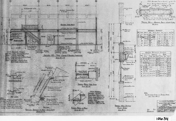
The image depicts a framed engineering or architectural drawing. The drawing is highly detailed, with various sections and notes included throughout. Visible are floor plans, cross-sections, elevation views, and structural details, indicating this might be a plan for a building or a component of an industrial system. There is a considerable amount of text annotating various features, dimensions, and construction notes, which are typical for architectural or engineering plans to communicate specifications to builders and tradespeople.
Annotations on the plan are made in a combination of handwritten and typed text, and there are tables and formulas included, which could relate to material properties or calculations necessary for the design. The document appears aged, with some discoloration and signs of wear, suggesting it could be a historical document or blueprints from an earlier era.
In the bottom right corner, there is an identification number "10L.34", which might be an archive, project, or file reference number. The plan is not only a technical document but might also have historical or educational significance, as it is framed and appears to be well preserved, perhaps for display or archival purposes.
Created by gpt-4o-2024-05-13 on 2024-12-07
This image shows a framed architectural or engineering drawing. The drawing contains multiple sections, elevations, and detailed annotations, labels, and measurements of a structural design. There are various calculations, tables, and notes indicating material specifications, dimensions, and construction methodologies. The setup seems technical, possibly related to construction or engineering projects. The details are meticulously marked with various lines, grids, and figures to direct the specifics of construction components. The presence of labels like "Windows Schedule," "Concrete Beam Schedule," and other detailed diagrams suggests that it might be a blueprint for a building or complex structural element. The drawing is labelled with a number "106.34" in the bottom right corner of the frame.
Anthropic Claude
Created by us.anthropic.claude-3-5-sonnet-20241022-v2:0 on 2025-06-25
This image appears to be an architectural or engineering drawing/blueprint. It shows various technical details, measurements, and specifications in what looks like a floor plan or structural layout. The drawing includes detailed dimensions, annotations, and what appears to be cross-sectional views. The document appears to be historical, given its black and white appearance and traditional drafting style. There are various notes and measurements written throughout the drawing, and it includes both plan views and detail drawings on the sides. The image has a reference number "106.34" visible at the bottom. The drawing style is typical of professional architectural or engineering documentation from before the era of computer-aided design (CAD).
Created by claude-3-haiku-20240307 on 2024-12-07
The image appears to be an architectural or engineering blueprint or schematic. It contains various technical drawings, measurements, and annotations that seem to depict the layout and details of a structure or facility. The image does not contain any human faces, so I will not attempt to identify or name any individuals. It appears to be a detailed technical diagram or plan, though without more context, I cannot determine the specific purpose or application of this particular document.
Created by claude-3-5-sonnet-20241022 on 2024-12-07
This appears to be an architectural or engineering drawing/blueprint showing various technical details, cross-sections, and measurements. The image is in black and white and contains multiple detailed diagrams including floor plans, structural elements, and dimensional notations. There are tables or schedules on the right side of the drawing that likely contain specifications or material lists. The drawing appears to be historical in nature, possibly from an older construction or renovation project. The document includes both plan views and sectional details with precise measurements and annotations throughout.
Meta Llama
Created by us.meta.llama3-2-11b-instruct-v1:0 on 2024-12-07
The image presents a detailed architectural drawing of a building, showcasing its floor plan and various features. The drawing is rendered in black and white, with a clear and concise layout that highlights the building's design elements.
Key Features:
- Floor Plan: The drawing provides a comprehensive view of the building's interior layout, including rooms, corridors, and staircases.
- Dimensions: The drawing includes precise measurements for each room and feature, allowing for accurate construction and renovation.
- Elevations: The drawing also includes elevations of the building's exterior, providing a detailed view of its facade and architectural style.
- Details: The drawing includes various details such as door and window openings, rooflines, and other architectural features.
Overall Impression:
The drawing appears to be a high-quality, professionally created architectural plan, likely used for construction or renovation purposes. The level of detail and precision suggests that it was created by a skilled architect or designer.
Created by us.meta.llama3-2-90b-instruct-v1:0 on 2024-12-07
The image presents a technical drawing of a building's floor plan, showcasing various sections and details. The drawing is rendered in black ink on a white background, with a black border surrounding it. The overall design suggests that this is an architectural or engineering blueprint.
Key Features:
- Floor Plan: The central focus of the drawing is the floor plan, which appears to be a single-story structure. The plan includes various rooms, corridors, and other features, such as doors, windows, and staircases.
- Sections: The drawing also includes several sections, which provide detailed views of specific parts of the building. These sections are labeled with letters and numbers, indicating their location within the overall plan.
- Details: In addition to the floor plan and sections, the drawing includes various details, such as measurements, materials, and construction methods. These details are scattered throughout the drawing, providing additional information about the building's design and construction.
- Scale: The drawing includes a scale, which allows the viewer to understand the proportions of the building. The scale is located in the bottom-right corner of the drawing and indicates that the drawing is to be read at a scale of 1:100.
- Date: The drawing is dated "106.34," which may refer to the date of creation or revision. However, without further context, it is difficult to determine the exact meaning of this date.
Conclusion:
In conclusion, the image presents a technical drawing of a building's floor plan, complete with sections, details, and a scale. The drawing provides a detailed view of the building's design and construction, making it a valuable resource for architects, engineers, and builders.
Amazon Nova
Created by amazon.nova-lite-v1:0 on 2025-02-24
The image is a technical drawing or blueprint, likely from an architectural or engineering context. It is a monochromatic, detailed plan that includes various sections and measurements. The drawing is divided into sections, each labeled with numbers and letters, such as "SECTION 35 - Thru Office & Record Storage" and "SECTION 36 - Main Service." The drawing includes a grid-like layout with dimensions and annotations in the form of text and numbers. The text includes terms like "Tropical Deck," "Concrete Slab," and "Steel Frame," indicating the materials and structural components involved. The drawing also contains a table with specifications, possibly for materials or components. The overall layout suggests a focus on structural integrity and material specifications for a building or construction project.
Created by amazon.nova-pro-v1:0 on 2025-02-24
The image depicts a technical drawing or blueprint of a building, likely an office or commercial space. The drawing is divided into multiple sections, each labeled with a specific section number and description. The sections include "Section 35 - Three Office & Record Room," "Section 36 - New Storage Room," and "Section 37 - New Storage Room." The drawing shows the floor plan, dimensions, and various architectural details of the building, such as walls, doors, windows, and other structural elements. The drawing is likely used for construction or renovation purposes, providing a detailed plan for the building's layout and design.
Google Gemini
Created by gemini-2.0-flash on 2025-04-29
Here's a description of the image based on the details you provided:
The image is a framed architectural drawing or blueprint. It is a black and white image, and the drawing appears to be quite detailed, with numerous lines, measurements, and annotations. Specific features that can be identified from the visible text and diagrams include:
- Section Views: There are cross-sectional views labeled as "SECTION 55 - THRU OFFICE & RECORDS STOREROOM" as well as "TYPICAL WALL SECTION".
- Detail Drawings: Sections are labeled "TYPICAL DETAIL OF NEW STAIRWAYS".
- Schedules: Schedules for both windows and columns.
- Note: There is a note that mentions something about fire insurance.
- Numerical Identification: The number "106.34" is clearly visible near the bottom right.
The drawing as a whole shows careful planning and design.
Created by gemini-2.0-flash-lite on 2025-04-29
The image is a blueprint or architectural drawing, likely for a building or structure. It is a detailed technical drawing with measurements, labels, and notations. The drawing features multiple views or sections, including details on construction elements like walls, stairs, and beams. There are also various tables and lists providing more information about materials, dimensions, and other specifications. The document appears to be vintage and is framed.
Mistral Pixtral
Created by us.mistral.pixtral-large-2502-v1:0 on 2025-05-27
The image depicts a detailed architectural drawing, likely a blueprint or a floor plan, for a building. Here are some key details and elements visible in the image:
Layout and Dimensions:
- The drawing includes various sections of the building, each labeled with specific dimensions.
- The dimensions are provided in feet and inches, indicating the size of different rooms and spaces.
Sections and Rooms:
- The plan shows different sections of the building, including rooms such as a basement, dining room, kitchen, and bedrooms.
- Specific areas like the dining room and kitchen are clearly marked, with details on fixtures and fittings.
Details and Annotations:
- The drawing includes detailed annotations and descriptions for various elements, such as doors, windows, and structural components.
- There are notes on materials and construction details, such as the type of wood to be used and specific instructions for construction.
Elevations and Cross-Sections:
- The drawing includes elevations and cross-sections to provide a clearer understanding of the building's structure and layout.
- These sections show the height and depth of various parts of the building, including walls and ceilings.
Legend and Symbols:
- The drawing uses standard architectural symbols and abbreviations to represent different elements, such as doors, windows, and structural supports.
- There are also notes on electrical and plumbing fixtures, indicating their placement within the building.
Scale and Measurements:
- The drawing is likely to scale, with measurements provided to ensure accurate construction.
- The scale is indicated, allowing for precise interpretation of the dimensions.
Additional Information:
- The drawing includes a title block with information such as the drawing number, date, and possibly the architect's or designer's name.
- There are also notes on revisions and changes made to the plan.
Overall, the image is a comprehensive architectural drawing that provides detailed information for the construction of a building, including layout, dimensions, materials, and construction details.
Qwen
Created by Qwen/Qwen2.5-VL-7B-Instruct on 2025-07-27
This image appears to be a technical architectural or engineering drawing, likely a blueprint or technical diagram. It includes various annotations, measurements, and detailed sections of what seems to be a structural design, possibly for a building or a part of infrastructure. The drawing contains several labeled sections and parts, with dimensions provided in feet and inches. There are notes and specifications that detail the materials, dimensions, and construction methods. The diagram also includes a table with codes or specifications, possibly related to materials or standards used in the design. The overall appearance suggests it is a professional document used for construction or engineering purposes.
Created by Qwen/Qwen2.5-VL-72B-Instruct on 2025-07-27
The image is a technical drawing or blueprint, likely related to construction or engineering. It appears to detail various sections of a structure, including walls, beams, and other architectural elements. The drawing includes multiple labeled sections, dimensions, and other specifications. There are also tables with numerical data, possibly related to materials or calculations. The blueprint is framed and has a reference number "106.34" in the bottom right corner. The overall appearance suggests it is a historical document, possibly from the mid-20th century, given the style of the drawing and the materials used.
Text analysis
Amazon