Machine Generated Data
Tags
Color Analysis
Feature analysis
Amazon
Clarifai

AWS Rekognition
| Monitor | 87.3% | |

Categories
Imagga
created on 2022-06-04
| text visuals | 91.5% | |
| interior objects | 3.6% | |
| streetview architecture | 2.6% | |
| paintings art | 1.2% | |
Captions
Microsoft
created by unknown on 2022-06-04
| a flat screen tv sitting on top of a blackboard | 56.9% | |
| a screen shot of a blackboard | 56.8% | |
| a blackboard near a monitor | 56.7% | |
Clarifai
No captions written
Salesforce
Created by general-english-image-caption-blip on 2025-05-21
a photograph of a black and white photo of a black and white drawing of a circuit board
Created by general-english-image-caption-blip-2 on 2025-07-02
a black and white photograph of a circuit diagram
OpenAI GPT
Created by gpt-4 on 2024-12-07
The image displays a black and white photograph of a schematic diagram or technical drawing. The design, which appears to be an electrical or mechanical engineering plan, features an array of interconnected lines, symbols, and text annotations indicating the components and the flow between them. The text and details are too small to read clearly in this view. The schematic is encased within a white border, which is possibly the edge of the paper or a mat framing the diagram, and there's a note or label in the lower right corner that suggests this document may pertain to a specific project or location, but the details are not legible. The drawing background is black, indicating that this might be a negative or a reversed image of the original schematic, as traditional blueprints or engineering drawings often have white lines on a blue background or black on white.
Created by gpt-4o-2024-05-13 on 2024-12-07
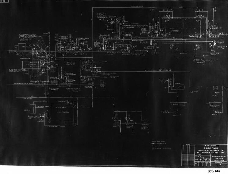
The image shows a technical piping diagram that appears to be drawn on a dark background. The diagram includes various technical details such as pipelines, valves, instruments, and equipment, all represented through detailed schematic symbols and annotations. In the bottom right corner, there is a title block that likely contains information such as the name of the project, the specific system or section of the plant that the diagram represents, and possibly the name of the company or engineer who prepared the drawing. The title block also includes grid references and a diagram number "105.50." This kind of diagram is typically used in engineering to plan and design the layout of piping systems in industrial plants, ensuring accurate construction and maintenance.
Anthropic Claude
Created by claude-3-haiku-20240307 on 2024-12-07
The image appears to be a detailed engineering or electrical schematic diagram, with complex circuitry and technical annotations displayed against a dark background. The diagram is monochromatic, with the intricate network of lines and text shown in black and white. This type of technical blueprint or wiring diagram is commonly used in engineering and manufacturing to provide a comprehensive visual overview of the components, connections, and specifications of a particular system or device.
Created by claude-3-5-sonnet-20241022 on 2024-12-07
This appears to be a technical piping diagram or schematic drawing, shown as a black and white blueprint or technical document. The image shows an intricate network of lines, symbols, and annotations representing what appears to be some kind of industrial or mechanical system layout. The diagram is quite complex, with multiple interconnected components spread across the drawing. It's presented in a traditional engineering drawing style with white lines on a dark background, typical of older technical documentation methods. At the bottom of the drawing, there appears to be a title block which likely contains project information and specifications, though the text is not clearly legible in this image.
Created by us.anthropic.claude-3-5-sonnet-20241022-v2:0 on 2025-06-26
This appears to be a technical piping diagram or schematic drawing, shown as a black and white negative image (white lines on black background). The drawing appears to be quite complex, with numerous interconnected lines, symbols, and annotations representing what seems to be an industrial piping system or process flow. The diagram includes various components and connections spread across the entire drawing space, with text labels and notations that are difficult to read at this resolution. At the bottom of the drawing, there appears to be a title block which is typical of engineering drawings, though the text is not clearly legible in this image. The overall layout suggests this is a professional technical drawing, possibly for an industrial or manufacturing facility.
Meta Llama
Created by us.meta.llama3-2-11b-instruct-v1:0 on 2024-12-07
The image presents a detailed technical drawing of a piping system, likely for a power plant or industrial facility. The drawing is rendered in white on a black background, with a white border surrounding it.
- Drawing Content:
- The drawing depicts a complex network of pipes and fittings, including valves, pumps, and other equipment.
- Various labels and annotations are scattered throughout the drawing, providing information about the different components and their functions.
- A key or legend in the bottom-right corner explains the symbols and abbreviations used in the drawing.
- Border and Background:
- The drawing is set against a black background, which helps to make the white lines and text stand out.
- A white border surrounds the drawing, adding a touch of contrast and making it easier to read.
- Overall Impression:
- The drawing appears to be a detailed and accurate representation of a real-world piping system.
- The level of detail and complexity suggests that it was created by a professional engineer or draftsman.
- The use of a black background and white lines gives the drawing a clean and professional look.
In summary, the image presents a technical drawing of a piping system, complete with detailed annotations and a clear key. The use of a black background and white lines makes the drawing easy to read and understand. Overall, the image suggests a high level of professionalism and attention to detail in its creation.
Created by us.meta.llama3-2-90b-instruct-v1:0 on 2024-12-07
The image depicts a black and white blueprint or technical drawing, likely related to piping systems. The drawing is presented on a dark background with white lines and text, featuring various symbols, labels, and annotations. A white border surrounds the drawing, which is set against a light gray background. In the bottom-right corner, a small section contains additional information, including a title, "PIPING DIAGRAM," and a location, "CARTON DE COLOMBIA, S.A., S.A. CALI, COLOMBIA, SOUTH AMERICA." The drawing also includes a scale, measurements, and other details relevant to the piping system it represents. Overall, the image appears to be a detailed technical illustration intended for professionals in the field of engineering or construction.
Amazon Nova
Created by amazon.nova-lite-v1:0 on 2025-02-24
The image appears to be a technical drawing or schematic diagram of an electrical system. It depicts various components and connections within the system, likely related to power distribution or control. The diagram is presented on a black background, with white lines and symbols representing different elements. The text "PIPING DIAGRAM POWER PLANT CARTON DE COLOMBIA S.A. CARTO COLOMBIA SOUTH AMERICA" is visible in the bottom right corner, indicating the source or context of the diagram. The image also includes a reference number "105.50" in the bottom left corner, possibly denoting a specific section or component within the system. Overall, the image conveys a technical and schematic nature, likely intended for engineers, technicians, or professionals involved in the design, installation, or maintenance of electrical systems.
Created by amazon.nova-pro-v1:0 on 2025-02-24
The image shows a piping diagram for a power plant, specifically for the Power Plant Carton de Colombia S.A. Call Colombia, South America. The diagram is a technical drawing that illustrates the layout and connections of the piping system within the power plant. It includes various components, such as valves, pipes, and equipment, arranged in a structured and organized manner. The diagram is likely used by engineers and technicians for planning, maintenance, and troubleshooting purposes.
Google Gemini
Created by gemini-2.0-flash on 2025-05-18
The image shows a technical drawing, specifically a piping diagram for a power plant. The drawing is mounted and framed. The diagram is quite detailed, filled with lines, symbols, and labels representing various pipes, valves, tanks, and other components of the plant's piping system. The drawing appears to be from Sargent & Lundy Engineers and is for a Carton de Colombia S.A. power plant in Cali, Colombia, South America. The drawing number appears to be M-3, and there's a control number 105.56 at the bottom right.
Created by gemini-2.0-flash-lite on 2025-05-18
Here's a description of the image:
The image shows a technical drawing, likely a blueprint or a similar type of architectural or engineering plan.
Here's a breakdown of what's visible:
- Content: The main focus is a complex diagram filled with lines, symbols, and text. It appears to be a "Piping Diagram" for a "Power Plant" in Cali, Columbia, South America. It likely illustrates the layout and connections of pipes and equipment within the power plant.
- Format: The drawing is presented on a large sheet, framed within a black border. There is a white border between the drawing and the black frame. The diagram itself is rendered in white against a dark (possibly black or navy blue) background. This is typical of blueprint-style drawings.
- Details: The drawing contains a multitude of technical symbols, text labels, and notations, indicative of detailed engineering information. The complexity suggests it is a detailed representation of a mechanical system.
- Labels and Markings: There is text at the bottom identifying it as the "Piping Diagram, Power Plant, Carton de Colombia S.A. Cali, Columbia, South America" The sheet also contains the engineers of the project "Sargent & Lundy" and a drawing number "M-3"
- Overall Impression: The image projects a sense of technical precision, professional engineering, and historical context.
Mistral Pixtral
Created by us.mistral.pixtral-large-2502-v1:0 on 2025-05-27
The image shows a detailed technical drawing, specifically a piping diagram. This type of diagram is commonly used in engineering and industrial settings to illustrate the layout and connections of piping systems within a facility. Here are some key details observed in the image:
Title and Identification:
- The title at the bottom right corner reads "PIPING DIAGRAM."
- The diagram is labeled for "ACETYLENE PLANT" and is associated with "Linde Air Products Co., S.A." located in "CALI, COLOMBIA, SOUTH AMERICA."
- There are specific drawing numbers and dates, indicating the version and updates of the diagram.
Diagram Layout:
- The diagram is complex, featuring numerous interconnected pipes, valves, and equipment.
- It includes various symbols and labels that represent different components such as pumps, tanks, compressors, and control valves.
- The layout is organized with lines and annotations that indicate the flow direction and connections between different parts of the system.
Legend and Scale:
- There is a legend or key that likely explains the symbols used in the diagram.
- A scale is provided to understand the relative sizes and distances within the piping system.
Annotations:
- The diagram includes detailed annotations and labels for each component, which help in identifying the specific parts and their functions within the system.
- There are likely notes on pressure, temperature, flow rates, and other operational parameters.
Framing:
- The diagram is framed with a black border, and there is a white margin around the drawing, which might be for handling or display purposes.
This type of diagram is crucial for the design, installation, maintenance, and operation of industrial piping systems, ensuring that all components are correctly connected and functioning as intended.
Qwen
Created by Qwen/Qwen2.5-VL-7B-Instruct on 2025-07-27
The image appears to be a technical drawing or blueprint, specifically a piping diagram for a power plant. The diagram is complex and includes numerous lines, symbols, and annotations that represent various components and connections within the power plant system. The text and labels are technical in nature, likely identifying parts of the system, flow paths, and operational details. The diagram is detailed and organized, indicating a structured approach to the design or layout of the power plant's piping system. The bottom right corner includes a label with the number "105.5" and other textual information, which might refer to a specific section or reference number within a larger set of drawings or documents.
Created by Qwen/Qwen2.5-VL-72B-Instruct on 2025-07-27
This image shows a technical diagram, specifically a piping diagram for a power plant. The diagram is presented on a black background with white lines and text, which gives it a high-contrast appearance. The diagram includes various lines, symbols, and annotations that represent different components and connections within the power plant system.
Key elements in the diagram include:
- Pipes and piping connections, indicated by lines and arrows.
- Valves and other control mechanisms, represented by specific symbols.
- Text labels and annotations providing details about the components and their functions.
- A grid in the bottom right corner, likely used for reference or scaling purposes.
- The title "Piping Diagram" and additional information such as the location "Cartagena, S.A. Cali Colombia, South America" and the company "Sargent & Lundy."
The overall layout is complex and detailed, typical of engineering or technical drawings used in industrial settings.
Text analysis
Amazon