Machine Generated Data
Tags
Color Analysis
Categories
Imagga
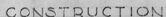
| text visuals | 100% | |
Captions
Microsoft
created on 2020-04-27
| a black and silver text on a white surface | 68.5% | |
| a close up of text on a white surface | 68.4% | |
| a black and silver text on a screen | 63.6% | |
OpenAI GPT
Created by gpt-4 on 2025-03-08
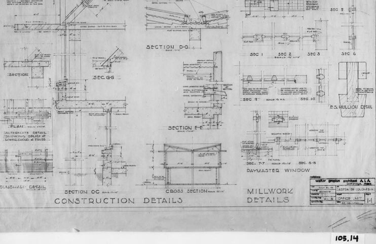
This image displays a framed architectural drawing or blueprint showing various construction details. The drawing includes a collection of sections, plans, and elevations of specific architectural elements, such as windows and their framing. The detail in the drawings shows the technical specifications, with dimensions and notes for construction guidance.
The title "CONSTRUCTION DETAILS" is prominently displayed, and the section below that contains the text "MILLWORK DETAILS." There are also references to specific sections marked as "SECTION," with subsequent letters and numbers (such as "SECTION A," "SECTION G-G," etc.) indicating various parts of the design being detailed.
In the bottom right-hand corner, there is a stamp or label with additional information, likely related to the project's architect, client, or builder, and possibly the date or identification number for the project ("I05.I4").
The drawing has a professional and technical quality, suggesting it was created for architectural or construction purposes, and the condition of the paper, as well as the style of the drawing, could indicate that it is from an older set of plans. The photograph captures the drawing positioned against a dark backdrop, allowing the details to stand out clearly.
Created by gpt-4o-2024-05-13 on 2025-03-08
The image shows an architectural drawing that includes detailed construction and millwork specifications. The drawing is labeled "CONSTRUCTION DETAILS" and "MILLWORK DETAILS" at the bottom, indicating that it contains various cross-sections, plans, and detailed views necessary for the construction and finishing of a building or structure.
Key elements in the drawing include:
Various Sections and Details: Several sections such as "SECTION D-D", "SECTION GG", and details like "Daymaster Window" and "Window... Double Hung Glazed in Place". These sections show cross-sectional views at different points in the construction, providing critical information about the dimensions, materials, and construction methods.
Measurement and Notations: Various measurements and notations are included throughout the drawing. These usually indicate dimensions, materials, and construction techniques needed to execute the construction plan.
Plan View: There appears to be a plan view of a floor or a segment of the building marked "PLAN".
Annotations and Labels: Parts of the drawing are labeled with annotations to provide further details.
Title Block: In the bottom right corner, there is a title block which might include information such as the project name, the sheets' date, the architect's details, and scale used for the drawing.
Frame: The page is neatly framed within black borders.
Overall, the image is indicative of highly detailed architect plans used by builders during the physical construction of a building.
Anthropic Claude
Created by claude-3-opus-20240229 on 2025-01-14
The image shows a detailed architectural blueprint or construction plan. It contains various cross-section views and diagrams depicting the structural components and millwork details of what appears to be a building, likely a residential home. The plans include measurements, material annotations, and callouts for specific construction elements such as windows, doors, and roof trusses. The blueprint is labeled "CONSTRUCTION DETAILS" at the bottom. The technical drawing style and level of detail suggests this is an official set of plans used to guide the building process.
Created by claude-3-haiku-20240307 on 2025-01-14
This image appears to be a detailed engineering or construction blueprint or technical drawing. It contains various sectional views, dimensions, and specifications related to construction details and millwork. The blueprint covers a range of architectural and structural elements, including a "Daymaster Window" and other components. The overall layout and level of technical detail suggest this is a professional engineering or architectural document intended for use in a construction or design project, rather than a general illustration or diagram.
Created by claude-3-5-sonnet-20241022 on 2025-01-14
This is an architectural drawing showing various construction and millwork details. The image appears to be a technical blueprint or construction document that includes multiple cross-sections, elevations, and detailed drawings. The sheet contains several labeled sections including "SECTION D-D," "SECTION E-E," and various other construction and millwork details. There appears to be specific attention paid to window details, marked as "DAYMASTER WINDOW" in one section. The drawing includes precise measurements and annotations throughout, typical of architectural construction documents. The image is in black and white and appears to be a historical or archived document, given its appearance and style.
Meta Llama
Created by us.meta.llama3-2-90b-instruct-v1:0 on 2025-01-14
This image is a black and white blueprint of a building's construction details, specifically focusing on the millwork. The blueprint is divided into sections, each labeled with a letter (e.g., "SECTION D-D") and accompanied by detailed drawings and measurements. The sections appear to depict various aspects of the building's design, including windows, doors, and other architectural features.
The blueprint also includes notes and annotations in the margins, which provide additional information about the construction process. The overall layout of the blueprint suggests that it was created for use by architects, engineers, or contractors involved in the building's design and construction.
The image has a gray background, with a black border around the blueprint. In the bottom-right corner, there is a small notation that reads "105.14," which may indicate the blueprint's identification number or a reference to a specific project or location. Overall, the image provides a detailed and technical view of the building's design and construction, highlighting the importance of careful planning and attention to detail in the architectural process.
Created by us.meta.llama3-2-11b-instruct-v1:0 on 2025-01-14
The image depicts a black-and-white blueprint of construction details for a building, specifically focusing on millwork. The blueprint is framed in black and features a white border around the edges, with the title "CONSTRUCTION DETAILS" at the bottom left and "MILLWORK DETAILS" at the bottom right.
Key Features:
- Title: The title "CONSTRUCTION DETAILS" is written in black text at the bottom left of the blueprint.
- Framing: The blueprint is framed in black and has a white border around the edges.
- Content: The blueprint contains various sections, including "SECTION D-D," "SECTION E-E," "SECTION CC," and "SECTION A-A." Each section includes detailed drawings and measurements of different elements, such as windows, doors, and walls.
- Measurements: The blueprint includes measurements for each section, providing precise dimensions for the construction of the building.
- Date: The date "DEC 4" is handwritten in the top-right corner of the blueprint.
- Number: The number "105.14" is handwritten in the bottom-right corner of the blueprint.
Overall:
The image provides a detailed and technical representation of the construction plans for a building, highlighting the importance of precision and accuracy in the construction process. The blueprint serves as a valuable resource for builders, architects, and engineers, ensuring that the final product meets the desired specifications and standards.
Amazon Nova
Created by amazon.nova-pro-v1:0 on 2025-01-14
The image is a technical drawing, likely an architectural or engineering blueprint, framed within a black border. The drawing is divided into multiple sections, each labeled with different section names such as "SECTION D-D," "SECTION G-G," "SECTION E-E," and "SECTION CC." These sections appear to be cross-sectional views of a structure, providing detailed insights into its construction. Each section includes various annotations, measurements, and labels that are typical in construction plans. The drawing also includes a title "CONSTRUCTION DETAILS" at the bottom, indicating that it is a detailed plan for building or modifying a structure. Additionally, there are references to specific materials and components, such as "DAYMASTER WINDOW" and "SUNSHADE DETAIL," suggesting that the structure may incorporate specialized architectural elements. The overall layout is organized, with clear delineations between different parts of the structure, facilitating a comprehensive understanding of the construction process.
Created by amazon.nova-lite-v1:0 on 2025-01-14
The image is a monochromatic architectural blueprint, likely from a construction project. It features a series of detailed sections and cross-sections, including "SECTION D-D," "SECTION C-C," and "CROSS SECTION." The blueprint also includes labels such as "SUNSHADE DETAIL," "MILLWORX," and "DAYMASTER WINDOW." Additionally, there are measurements and notes, such as "DEC. 7-7" and "DEC. 6-6." The blueprint is framed in black and white, with a title at the bottom left corner reading "CONSTRUCTION DETAILS."
Created by amazon.nova-lite-v1:0 on 2025-01-12
The image is a technical drawing, likely from an architectural or engineering blueprint, featuring a detailed section of construction details. The drawing is divided into multiple sections, each labeled with a section number and title, such as "SECTION D-D," "SECTION E-E," and "SECTION C-C." These sections show various structural components and their arrangements, including beams, columns, and other elements. The drawing includes annotations and measurements, indicating dimensions and specifications for each component. The drawing also includes a table at the bottom with additional details, possibly related to materials or construction methods. The overall appearance of the drawing suggests it is a part of a larger set of plans for a construction project.
Created by amazon.nova-pro-v1:0 on 2025-01-12
The image depicts a detailed architectural drawing of a building. The drawing is divided into several sections, each labeled with a letter and number combination, such as "SEC. G-G" and "SEC. C-C." These sections likely represent different cross-sections or elevations of the building. The drawing includes various annotations, measurements, and construction details, indicating the structural elements, dimensions, and materials used in the construction. The overall layout suggests a comprehensive architectural plan for a building project.
Text analysis
Amazon