Machine Generated Data
Tags
Color Analysis
Feature analysis
Amazon
Clarifai
AWS Rekognition
| Monitor | 98.2% | |

Categories
Imagga
created on 2022-06-04
| text visuals | 44.2% | |
| streetview architecture | 26.9% | |
| interior objects | 22.2% | |
| paintings art | 2.4% | |
| food drinks | 2.1% | |
| pets animals | 1% | |
Captions
Microsoft
created by unknown on 2022-06-04
| a screen shot of a computer monitor sitting on top of a desk | 30.2% | |
| a screen shot of a computer | 30.1% | |
| a screen shot of a computer monitor | 30% | |
Clarifai
No captions written
Salesforce
Created by general-english-image-caption-blip on 2025-05-20
a photograph of a black and white photograph of a black and white drawing of a building
Created by general-english-image-caption-blip-2 on 2025-06-28
a black and white photograph of a blueprint
OpenAI GPT
Created by gpt-4 on 2024-12-08
This is an image of a black-and-white architectural drawing or blueprint. The blueprint is detailed with numerous lines, symbols, and annotations that indicate dimensions, structures, and possibly the layout of a building or a machine. The drawing is on a dark background with white or light-colored lines and text, which is typical of a negative image of a traditional blueprint. On the right side, there are columns with numerical and text data, possibly measurements or specifications related to the drawing. The image is mounted on a board or mat, with white edges visible around the perimeter of the blueprint.
There's a number, "107.94," in the bottom right corner which may signify a reference or identification number for the blueprint. The content of the blueprint is not entirely clear from the image due to the lack of detail and the angle at which the photo was taken.
Created by gpt-4o-2024-05-13 on 2024-12-08
This image appears to be a detailed engineering or architectural blueprint or technical drawing. It features a grid layout labeled with letters and numbers, likely representing structural components such as beams or columns. There are various technical annotations and labels throughout the drawing, as well as some additional sections and details shown on the bottom and right side of the sheet. These sections likely provide close-up views or specifications for particular parts of the design, such as joints or connections. The drawing is on a dark background, possibly indicating it was originally a white-on-black blueprint copy. Annotations and tables on the right likely include material specifications or dimensions associated with the structure. There are handwritten and printed elements and a section at the bottom with smaller detailed diagrams. The document is overall very technical and would likely require domain-specific knowledge to interpret fully.
Anthropic Claude
Created by us.anthropic.claude-3-5-sonnet-20241022-v2:0 on 2025-06-24
This image appears to be a technical or engineering blueprint or schematic drawing. It's a black and white document with white lines and text on a dark background, similar to a photographic negative. The drawing contains what looks like detailed technical specifications, measurements, and diagrams. There appear to be grid patterns, numerical data, and various technical notations spread across the document. The image has a reference number "187.96" visible at the bottom. The overall layout suggests this could be an architectural, engineering, or construction drawing, though the specific details are difficult to make out due to the image quality and inverted coloring.
Created by claude-3-haiku-20240307 on 2024-12-08
The image appears to be an engineering or technical diagram. It shows a grid-like layout with numerous numerical values, calculations, and annotations. The overall image is in black and white, with the grid lines and text appearing in a stark black against a light gray background. Without being able to identify any specific individuals, the image seems to be a detailed technical schematic or drawing of some kind of engineering or scientific diagram.
Created by claude-3-5-sonnet-20241022 on 2024-12-08
This appears to be a technical blueprint or architectural drawing in negative (white lines on black background). The image shows a detailed grid pattern with various measurements and annotations. There appears to be structural or engineering details, including what look like cross-sections and dimensional specifications. On the right side of the image, there's what appears to be a table or chart with numerical data. The drawing has multiple detailed sections with various technical notations and measurements throughout. The overall composition suggests this might be a construction or engineering document, possibly for building or infrastructure planning. The number "189.96" is visible in the bottom right corner.
Meta Llama
Created by us.meta.llama3-2-11b-instruct-v1:0 on 2024-12-08
The image is a black-and-white photograph of a blueprint, featuring a white border and a black frame. The blueprint itself is black with white text and lines, and it appears to be a technical drawing or diagram. The background of the image is a light gray color, which suggests that it may have been taken in a studio or office setting.
Key Features:
- Blueprint: The main focus of the image is the blueprint, which is a technical drawing or diagram.
- White Border: The blueprint has a white border around it, which helps to separate it from the rest of the image.
- Black Frame: The blueprint is surrounded by a black frame, which adds depth and contrast to the image.
- Light Gray Background: The background of the image is a light gray color, which provides a neutral and clean backdrop for the blueprint.
Overall Impression:
The image suggests that the blueprint is an important document or artifact, possibly related to a specific project or industry. The use of a black-and-white color scheme and a formal frame suggests a sense of professionalism and expertise. The image may be used in a variety of contexts, such as in a museum or archive, or in a professional setting where technical drawings are used.
Created by us.meta.llama3-2-90b-instruct-v1:0 on 2024-12-08
The image is a black-and-white photograph of a blueprint or technical drawing, likely from an architectural or engineering project. The drawing is presented on a white background with a black border, and it features a grid pattern with various symbols, lines, and text.
Key Features:
- Grid Pattern: The drawing has a grid pattern with horizontal and vertical lines, which are likely used to scale and measure the design.
- Symbols and Lines: There are various symbols and lines throughout the drawing, including rectangles, triangles, and circles. These symbols may represent different components or features of the design.
- Text: There is text written in the bottom-right corner of the drawing, which appears to be a date or code. The text reads "107.96" and may indicate the version or revision number of the drawing.
- Background: The background of the image is a light gray color, which provides a neutral contrast to the black and white drawing.
Overall Impression:
The image suggests that the drawing is a detailed and technical representation of a design or plan. The use of a grid pattern, symbols, and text indicates that the drawing is intended to convey specific information and measurements. The presence of a date or code in the bottom-right corner implies that the drawing may be part of a larger project or series of revisions.
Amazon Nova
Created by amazon.nova-lite-v1:0 on 2025-02-24
The image features a document with a grid-like structure, possibly a table or a form. The document appears to be a technical or engineering document, given its structured and organized format. The grid is filled with various text entries, numbers, and symbols, indicating a detailed and systematic approach to the information presented. The text and numbers are organized in rows and columns, with some rows and columns containing more detailed information than others. The document has a black border around it, and the background is a neutral gray color, which helps to highlight the content of the document.
Created by amazon.nova-pro-v1:0 on 2025-02-24
The image shows a black-and-white architectural plan of a building. The plan is drawn on a black sheet of paper, and it contains various details, including dimensions, measurements, and annotations. The plan is divided into different sections, such as the floor plan, elevation, and structural details. The floor plan shows the layout of the rooms and spaces within the building, while the elevation provides a side view of the building's exterior. The structural details include information about the building's foundation, walls, and roof. The plan also includes annotations and notes that provide additional information about the building's design and construction.
Google Gemini
Created by gemini-2.0-flash on 2025-04-29
Here is a description of the image:
The image presents a detailed technical drawing on a dark background, framed by a black and white border. The drawing appears to be an architectural or engineering plan, possibly a blueprint, with numerous lines, symbols, and text arranged in a grid-like format.
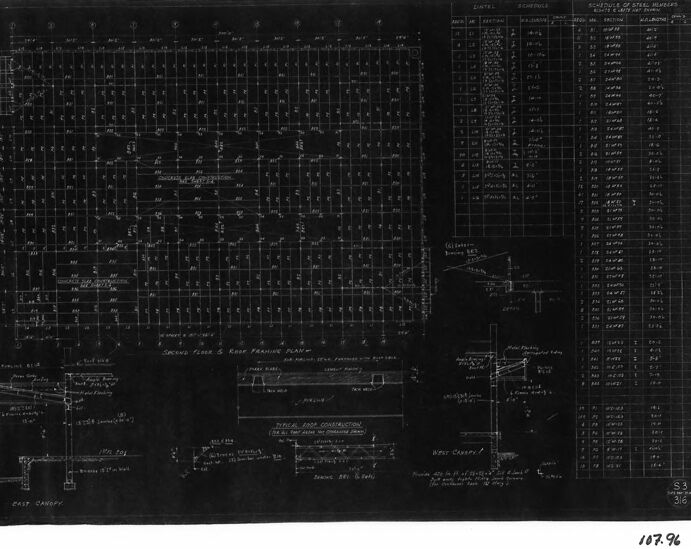
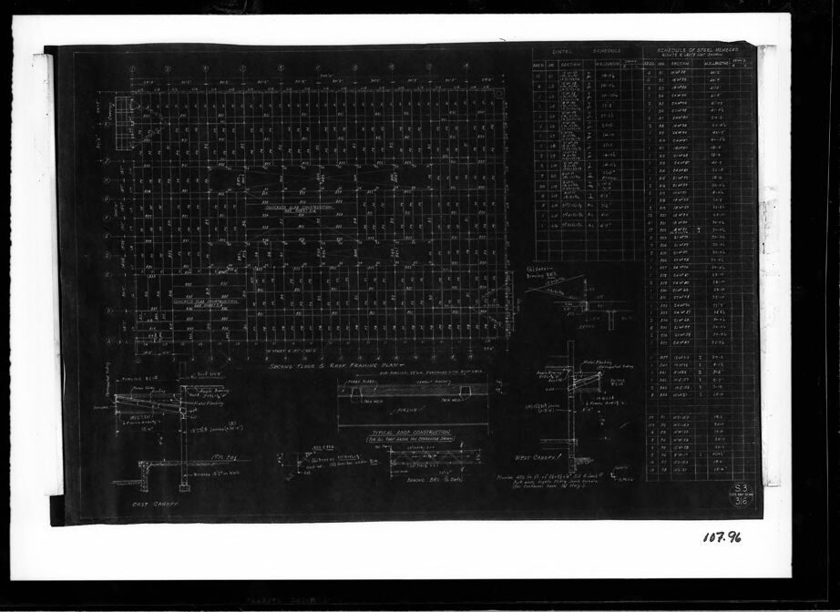
The layout includes what seems to be a floor plan at the top, labeled as "SECOND FLOOR & ROOF FRAMING PLAN," with a grid of points and lines indicating the structural elements. Below this, there are several smaller diagrams, including sections labeled "EAST CANOPY" and "WEST CANOPY," along with other details that could represent construction specifications or components.
A table with multiple columns and rows is visible on the right side, likely a schedule or list of materials, labeled as "SCHEDULE OF STEEL MEMBERS." The rows contain numerical and textual data, possibly indicating quantities, dimensions, or other specifications.
The technical drawing is marked with numbers like "S3" and "3/6" and "107-96".
Created by gemini-2.0-flash-lite on 2025-04-29
The image is a blueprint, framed and matted, depicting architectural plans. The central focus is on a detailed plan view, likely of a building's structure. Numerous lines, symbols, and notations fill the drawing. To the right, there's a schedule listing detailed specifications. Below the main plan, several smaller diagrams provide sectional views and construction details. Text labels and dimensions are scattered throughout the drawing, which is in white against a black background.
Mistral Pixtral
Created by us.mistral.pixtral-large-2502-v1:0 on 2025-05-27
The image appears to be a detailed technical drawing or blueprint, likely related to a mechanical or electrical system. Here are some observations:
Layout and Sections:
- The drawing is divided into multiple sections, each labeled with different components or parts of the system.
- There are clear demarcations and labels indicating various parts and their functions.
Components and Labels:
- The drawing includes labels such as "Second Time & Keep Pressure Plate," "Print Camshaft," and "WPC Clutch."
- There are detailed annotations and measurements, suggesting precise engineering specifications.
Grid and Dimensions:
- The drawing is overlaid with a grid, which helps in accurately placing and measuring components.
- Dimensions and scales are likely included to ensure proper sizing and placement of parts.
Technical Details:
- The right side of the drawing includes a table or list with numerical values and descriptions, possibly related to control settings or component specifications.
- There are intricate line drawings and symbols representing mechanical or electrical components and their connections.
Purpose:
- The drawing seems to be a part of a larger technical document, possibly for manufacturing, assembly, or maintenance of a complex system.
- It could be related to industries such as aerospace, automotive, or machinery, where precise technical drawings are essential.
Overall, the image is a comprehensive technical blueprint designed for engineers or technicians to understand the layout, components, and specifications of a mechanical or electrical system.
Qwen
Created by Qwen/Qwen2.5-VL-7B-Instruct on 2025-07-27
The image is a black and white technical drawing or blueprint. It appears to be a structural or architectural drawing, likely related to a building or construction project.
Main Section: The central part of the drawing features a detailed grid layout that represents a floor plan or structural grid. It is marked with various codes, numbers, and lines that suggest measurements and specifications for the structure.
Details and Labels: There are labeled sections and annotations that provide specific information about the construction, such as "Typical Area Construction" and other labeled areas indicating different parts of the structure like "East Canopy" and "West Canopy."
Tables and Specifications: On the right side of the drawing, there is a table or schedule titled "Schedule of Steel Members," which lists details such as steel section, depth, and weight, along with other specifications.
Other Elements: There are additional drawings and notes at the bottom left, which seem to provide further details or instructions about specific parts of the design.
This type of drawing is typically used by engineers or construction teams to plan and execute the construction of a building accurately. The precise nature and scale of the grid and the detailed annotations suggest it is a technical drawing meant for precise construction planning.
Created by Qwen/Qwen2.5-VL-72B-Instruct on 2025-07-27
This image is a framed architectural blueprint or construction plan. The blueprint appears to be a black-and-white drawing, likely on a dark background with light ink used for the lines and text, which is a common style for certain types of technical drawings.
The blueprint contains several sections:
Grid and Layout: The main part of the blueprint shows a grid layout, which is likely representing the floor plan of a building. The grid is composed of intersecting lines, and there are various numbers and annotations within the grid, indicating dimensions, room numbers, or other details.
Schedule of Steel Members: On the right side of the blueprint, there is a section labeled "SCHEDULE OF STEEL MEMBERS." This section includes a table with columns and rows, listing different steel members used in the construction. The table provides details such as the type of steel, dimensions, and possibly the quantity or location of each member.
Notes and Annotations: There are various notes and annotations scattered throughout the blueprint. These notes likely provide additional information about the construction details, such as specifications for materials, construction methods, or other relevant instructions.
Title Block: In the bottom right corner, there is a title block with the number "107.96" and possibly other information such as the project name, architect, or drawing date.
The blueprint is mounted within a white mat and a black frame, which helps to highlight the details of the drawing. The overall presentation suggests that this is a professional and detailed architectural or engineering document.
Text analysis
Amazon