Machine Generated Data
Tags
Color Analysis
Feature analysis
Amazon
Clarifai

AWS Rekognition
| Monitor | 82.3% | |

Categories
Imagga
created on 2022-06-04
| text visuals | 82.1% | |
| streetview architecture | 13.8% | |
| interior objects | 3.1% | |
Captions
Microsoft
created by unknown on 2022-06-04
| a flat screen tv sitting on top of a desk | 53.7% | |
| a flat screen monitor | 53.6% | |
| a screen shot of a computer monitor | 53.5% | |
Clarifai
No captions written
Salesforce
Created by general-english-image-caption-blip-2 on 2025-06-29
a black and white photograph of a blueprint of a bridge
Created by general-english-image-caption-blip on 2025-05-03
a photograph of a black and white photo of a building with a blueprinted drawing of a
OpenAI GPT
Created by gpt-4 on 2024-12-07
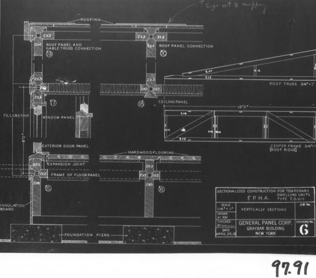
This image features a framed architectural drawing or blueprint displayed in a black-and-white photograph. The blueprint contains detailed diagrams and annotations pertaining to a construction project, specifically focusing on sectionalized construction from temporary war emergency dwellings by the Federal Public Housing Authority (FPHA), Type L-041 units.
The various sections of the drawing illustrate components such as roofing, a roof panel and gable truss connection, window panels, exterior door panels, an expansion joint, the frame of a floor panel, foundation piers, and other architectural details. There are also explanatory texts and measurements providing specifications for the construction.
The photograph includes a drawing scale and the name of the company responsible for the blueprint, General Panel Corp. of New York, along with a logo on the bottom right. There is a handwritten note at the top right corner of the picture, which appears to be a reference or archive number of some sort. At the bottom right of the photo, outside the frame of the blueprint but within the photo's border, a numerical code "9.91" is visible, suggesting it may be an identifying number or code for the image or item itself. The overall presentation suggests that this document is part of an archive or collection.
Created by gpt-4o-2024-05-13 on 2024-12-07
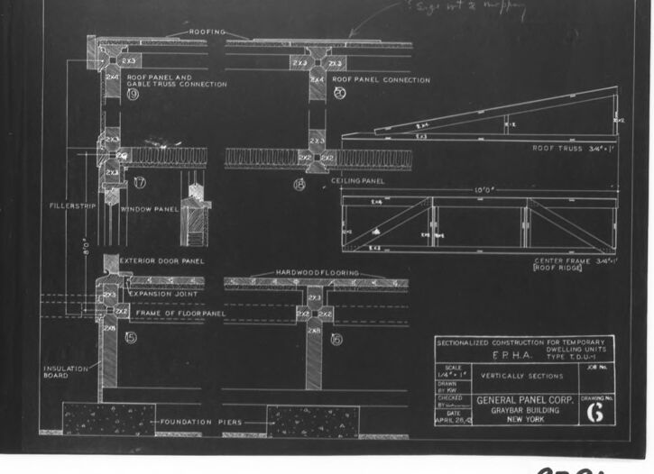
This image depicts a detailed architectural drawing or blueprint created by the General Panel Corporation. The blueprint is labeled "Sectionalized Construction for Temporary Dwelling Units, E.P.H.A. Type F.U. 4-1" and is dated April 21, 1944, with a drawing number of 6.
The blueprint shows several vertical sections, each labeled and dimensioned with clear instructions and measurements. Some key components and sections depicted include:
- Roof panel and gable truss connection
- Roof truss
- Ceiling panel
- Center frame (roof ridge)
- Exterior door panel
- Window panel
- Expansion joint
- Frame of the floor panel
- Hardwood flooring
- Foundation piers
- Insulation board
- Roof panel connection
Various materials and dimensions, such as 2"x3" and specific angles, are indicated to guide construction. The blueprint appears to be a technical drawing intended for precise construction and assembly instructions for temporary dwelling units.
Anthropic Claude
Created by us.anthropic.claude-3-5-sonnet-20241022-v2:0 on 2025-06-25
This image appears to be an architectural or engineering blueprint/drawing, specifically showing various construction details and vertical sections. It's a technical drawing on a dark background with white lines, showing detailed cross-sections of building components including:
- Roofing details and roof panel connections
- Ceiling panel specifications
- Window panel details
- Exterior door panel construction
- Floor panel framing
- Foundation details
- Insulation board placement
The drawing includes precise measurements and annotations, and appears to be for a FPHA (Federal Public Housing Authority) temporary dwelling unit. The scale and other technical information is shown in a title block in the lower right corner, and it's labeled as "General Panel Corp." drawing. The drawing is numbered "G" and shows various construction joints and connection details that would be used in modular or prefabricated construction.
Created by claude-3-haiku-20240307 on 2024-12-07
The image appears to be an architectural blueprint or construction drawing. It contains various detailed plans and sectional views of a building structure, including details for the roof, walls, windows, doors, and foundation. The drawing seems to be for a temporary or modular dwelling unit, as indicated by the text "TEMPORARY DWELLING UNITS FPMA T-3 HOUSES". The plans provide technical specifications and dimensions for the different components of the structure.
Created by claude-3-5-sonnet-20241022 on 2024-12-07
This is an architectural blueprint or technical drawing showing vertical sections of a building construction detail. It appears to be from the FPHA (Federal Public Housing Authority) and is labeled as "Sectionalized Construction for Temporary Dwelling Units." The drawing shows various construction elements including:
- Roofing details and roof panel connections
- Ceiling panel specifications
- Window panel details
- Exterior door panel components
- Hardwood flooring
- Foundation piers
- Insulation board placement
The drawing includes precise measurements and construction specifications, and appears to be drawn to scale (1/4"=1'). In the top right corner, there are additional details showing roof truss configurations and center frame sections. The drawing is marked as sheet "6" and was produced by the General Panel Corporation for what appears to be a modular or prefabricated building system. The image is in the typical blueprint style with white lines on a dark background.
Meta Llama
Created by us.meta.llama3-2-11b-instruct-v1:0 on 2024-12-07
The image presents a technical drawing of a building's floor plan, showcasing the layout and design of the structure. The drawing is rendered in black and white, with various elements labeled for clarity.
Key Features:
- Roofing: The roof is depicted as a flat surface, with a slight slope to allow for water runoff.
- Roof Panel and Cable Truss Connection: This section illustrates the connection between the roof panels and the cable truss system, which provides additional support to the roof.
- Fillerstrip: A fillerstrip is shown between the roof panels, serving as a gap filler to ensure proper alignment and sealing.
- Window Panel: The window panel is depicted as a rectangular shape, with a frame and sash that can be opened for ventilation or light entry.
- Exterior Door Panel: The exterior door panel is shown as a rectangular shape, with a frame and hinges that allow it to swing open and closed.
- Expansion Joint: An expansion joint is illustrated between the exterior door panel and the wall, allowing for movement and expansion of the structure due to temperature changes or other factors.
- Frame of Floor Panel: The frame of the floor panel is depicted as a rectangular shape, with joists and beams that provide structural support to the floor.
- Insulation Board: Insulation board is shown between the floor panel and the foundation piers, serving as a thermal barrier to reduce heat transfer and improve energy efficiency.
- Foundation Piers: The foundation piers are depicted as vertical columns that transfer the weight of the building to the ground, providing stability and support to the structure.
Additional Details:
- Sectionalized Construction: The drawing notes that the construction is sectionalized, indicating that the building is designed to be constructed in sections or modules, which can be assembled on-site.
- Temporary Dwelling Units: The drawing specifies that the construction is for temporary dwelling units, suggesting that the building is intended for short-term use or as a temporary solution.
- General Panel Corp.: The drawing is attributed to General Panel Corp., a company that specializes in panelized construction systems.
- Graybar Building: The drawing is dated April 28, 1941, and is labeled as a "Graybar Building" project, indicating that it was created for a specific client or project.
Overall, the image provides a detailed and technical representation of a building's floor plan, highlighting the various components and features that make up the structure.
Created by us.meta.llama3-2-90b-instruct-v1:0 on 2024-12-07
The image depicts a black-and-white architectural drawing of a building's floor plan, featuring various sections and components. The drawing is presented on a white background with a black border, and it includes labels and measurements for different parts of the structure.
Key Features:
- Floor Plan: The main focus of the image is the floor plan, which shows the layout of the building's interior spaces.
- Sections and Components: The drawing includes various sections and components, such as walls, doors, windows, and roof panels.
- Labels and Measurements: The image features labels and measurements for different parts of the structure, providing detailed information about the building's design and construction.
- Background and Border: The drawing is presented on a white background with a black border, which helps to highlight the details of the floor plan and its components.
Conclusion:
In summary, the image presents a detailed architectural drawing of a building's floor plan, showcasing its various sections and components. The inclusion of labels and measurements provides valuable information about the structure's design and construction, making it a useful resource for architects, builders, and anyone interested in understanding the intricacies of building design.
Amazon Nova
Created by amazon.nova-lite-v1:0 on 2025-02-25
The image shows a technical drawing or blueprint of a building's structural components. The drawing is labeled "SECTIONALIZED CONSTRUCTION FOR TEMPORARY DWELLING UNITS" and "TYPE EDGH-1" and is dated April 28, 1991. The drawing depicts various components of the building, including the foundation, walls, roof, and interior elements.
The foundation is shown as a series of piers, and the walls are constructed using a modular panel system. The roof is supported by trusses, and the interior includes elements such as ceiling panels, insulation, and flooring. The drawing also includes details such as the location of electrical outlets and the dimensions of various components.
The drawing is labeled "GENERALLY PANEL CORP. GRA NEW YORK" and includes a drawing number "92.91". The image appears to be a technical document used for construction or engineering purposes, providing detailed information about the building's design and construction.
Created by amazon.nova-pro-v1:0 on 2025-02-25
The image depicts a technical drawing of a building's construction details, specifically focusing on the roofing and structural components. The drawing is presented in black and white, with annotations and labels detailing various elements of the structure. The drawing includes sections of the roof, roof panels, trusses, and other structural elements. The annotations indicate dimensions, materials, and construction methods. The drawing is framed within a black border and appears to be a professional architectural or engineering document.
Google Gemini
Created by gemini-2.0-flash on 2025-04-28
Here's a description of the image:
This is a black and white image of an architectural blueprint. It depicts sectionalized construction for temporary dwelling units, identified as "Type T.O.U-1" by E.P.H.A. The blueprint is labeled "Vertically Sections" with a scale of "1/4"=1'".
The drawing details various components of a building structure, including:
- Roofing
- Roof panel connections and gable truss connections
- Ceiling panel
- Window panel
- Exterior door panel
- Hardwood flooring
- Frame of the floor panel
- Expansion joint
- Insulation board
- Foundation piers
Additionally, the drawing includes diagrams of:
- A roof truss labeled "Roof Truss 3/4"=1'"
- A center frame or roof ridge labeled "Center Frame 3/4"=1'[Roof Ridge]"
The blueprint indicates it was created by General Panel Corp., located in the Graybar Building in New York. The drawing number is "6," and there's a reference number "97.91" at the bottom. There are handwritten notes near the top.
Created by gemini-2.0-flash-lite on 2025-04-28
Here's a description of the image:
Overall:
The image is a technical drawing, likely an architectural blueprint or engineering plan. It's a sectional view, providing details on how a structure is constructed from the inside.
Specific Elements and Details:
- View Type: The drawing appears to be a vertical section, showing the layers and components of a building's construction from the foundation to the roof.
- Labeled Components: Numerous components are labeled in the drawing, including:
- Roofing
- Roof Panels and connections
- Gable Truss Connection
- Ceiling Panel
- Window Panel
- Exterior Door Panel
- Hardwood Flooring
- Frame of Floor Panel
- Expansion Joint
- Foundation Piers
- Insulation Board
- Roof Truss
- Center Frame (roof ridge)
- Annotations: The image is marked with numbers in circles (e.g., 9, 10, etc.), which likely correspond to specific features or connections.
- Scale: The drawing includes a scale, stating that 1/4 inch = 1 foot.
- Title and Purpose: The drawing is titled "SECTIONALIZED CONSTRUCTION FOR TEMPORARY DWELLING UNITS" and is identified as "TYPE T.O.U.-1" It specifies "E.P.H.A" which might stand for something related to the project.
- Company/Organization: The drawing is from "GENERAL PANEL CORP." located in "GRAYBAR BUILDING, NEW YORK."
- Drawing Number: The drawing's number is "6."
- Date: The image is dated with "APRIL 28,C."
- Notes: There is a handwritten note "sage wit & m/pry"
Overall Impression:
The image represents a detailed plan for constructing temporary housing units. The sectional view is meant to give builders or engineers a clear understanding of the building's structure, materials, and assembly process. The precision and labeling suggest this is a professional document intended for building or manufacturing.
Mistral Pixtral
Created by us.mistral.pixtral-large-2502-v1:0 on 2025-04-28
This image is a detailed architectural drawing, specifically a sectionalized construction plan for a temporary building. Here's a breakdown of the key elements depicted in the drawing:
Roofing and Trusses:
- The roofing is shown with specific details about the roof panels and their connections.
- There is a roof panel and double truss connection, as well as a roof panel connection.
- A roof truss is illustrated with a 3:4"/1" slope.
Ceiling and Panels:
- A ceiling panel is depicted, showing its placement and connection details.
- There is a filler strip indicated between certain panels.
Wall and Window Panels:
- The drawing includes a window panel and an exterior door panel.
- The wall panels are shown with specific connections and joints, such as an expansion joint.
Flooring and Foundation:
- Hardwood flooring is indicated, supported by a frame of floor panels.
- Foundation piers are shown at the base, providing structural support.
- An insulation board is also depicted below the flooring.
Structural Details:
- Various structural elements are labeled, such as the center frame and roof ridge.
- Specific dimensions and angles are provided for the trusses and other structural components.
Identification and Specifications:
- The drawing is labeled as "Sectionalized Construction for Temporary Housing" under the F.P.H.A. (Federal Public Housing Authority) Type C.D.U.-6.
- It includes details about the drawing number (97.91), the company (General Panel Corp.), the building type (Gravham Building), and the date (10-27-42).
Overall, this drawing provides a comprehensive view of the structural and material components of a temporary housing unit, detailing how various parts are connected and supported.
Qwen
Created by Qwen/Qwen2.5-VL-7B-Instruct on 2025-07-26
The image is a technical blueprint or architectural drawing that appears to detail the construction of a temporary dwelling unit. The drawing includes various labeled sections of the structure, such as the roof, roof panel connections, trusses, ceiling panel, and exterior door panel. It also specifies the construction of the floor panels, including expansion joints and insulation. The scale of the drawing is noted as 1/4" = 1'. The drawing is from General Panel Corp., Graybar Building, New York, and is dated April 28, 1941. The blueprint is sectioned vertically to show different components of the dwelling. There is a handwritten note at the top that seems to indicate a change or modification to the drawing, possibly adding "2" to the existing "1" and "1/2".
Created by Qwen/Qwen2.5-VL-72B-Instruct on 2025-07-26
This image is a black and white architectural blueprint or construction drawing. It appears to depict various construction details and specifications for a temporary dwelling unit. The drawing includes labeled sections and cross-sectional views of different parts of the structure, such as the roof panel and gable truss connection, ceiling panel, window panel, exterior door panel, and foundation piers.
Key components of the drawing include:
- Roofing and roof truss details.
- Ceiling and wall panel construction.
- Window and door panel specifications.
- Hardwood flooring and floor panel frame details.
- Foundation piers and insulation board.
The drawing is labeled with dimensions and notes, and there is a legend in the bottom right corner that includes the scale, drawing number, and the company responsible for the drawing, "General Panel Corp." The date on the drawing is April 29, 1943. The image also has a handwritten note in the top right corner and a number "97.91" in the bottom right corner.
Text analysis
Amazon