Machine Generated Data
Tags
Color Analysis
Feature analysis
Amazon
Clarifai
AWS Rekognition
| Monitor | 85.1% | |

Categories
Imagga
created on 2022-06-04
| text visuals | 83.4% | |
| interior objects | 13% | |
| streetview architecture | 2.2% | |
Captions
Microsoft
created by unknown on 2022-06-04
| a screen shot of a computer | 67.7% | |
| a screen shot of a monitor | 55.2% | |
| a screen shot of a computer monitor | 45.4% | |
Clarifai
No captions written
Salesforce
Created by general-english-image-caption-blip on 2025-05-21
a photograph of a black and white photo of a black and white photo of a building
Created by general-english-image-caption-blip-2 on 2025-06-28
a black and white photo of a blueprint of a building
OpenAI GPT
Created by gpt-4 on 2024-12-07
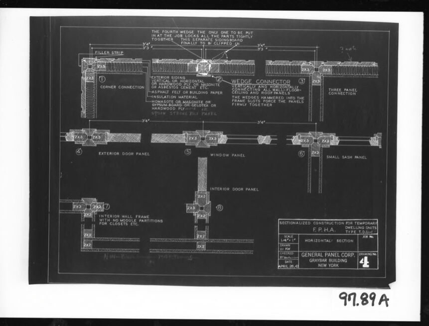
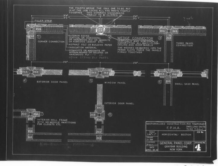
This image shows a black and white photograph of a framed technical drawing. The drawing appears to be an architectural blueprint or construction plan detailing various types of panels and connections for a building. There are multiple labeled sections within the drawing, such as "Exterior Door Panel," "Window Panel," "Interior Door Panel," "Filler Stripe," "Wedge Connector," "Exterior Siding," "Interior Wall Frame," among others. The labels and dimensions suggest that this could be a modular construction system or a prefabricated building design. At the bottom right of the drawing, there's a label that reads "Sectionalized Construction for Temporary F.P.H.A. Type E-1 Dwellings. General Panel Corp. Gramercy Building, New York."
The alphanumeric code "91.89A" is visible at the bottom right corner of the photograph, which likely serves as a reference number for the document or photograph itself. The text and details on the blueprint are etched in white on a dark background, which is typical for blueprints when photographed or reproduced in this style. The entire drawing is framed with a white border, encased within a black frame.
Created by gpt-4o-2024-05-13 on 2024-12-07
The image displays a technical architectural drawing of a building panel system. This drawing, marked with the code "97.89A" seems to be focused on illustrating various types of panel connections and sections. It includes the following key features:
- Corner Connection - Diagram showing how panels fit at a corner with detailed specifications.
- Wedge Connector - Details on panel connections using wedges.
- Three Panel Connection - Diagram illustrating a connection involving three panels meeting.
- Exterior Door Panel - Section detail of an exterior door panel.
- Window Panel - Detailed drawing of a window panel section.
- Small Sash Panel - Depiction of a small sash panel corner.
- Interior Wall Frame with L-40 Module Partitions for Closets - Illustration of interior wall framing for modular partitions.
The diagram also features materials specifications such as "exterior siding," "insulation material," and "horizontal section" notes. The bottom right corner indicates that the drawing is from General Panel Corp., located in the Graybar Building, New York, and it was approved on April 25, 1945. The scale is listed as 1/4 inch = 1 foot.
Anthropic Claude
Created by us.anthropic.claude-3-5-sonnet-20241022-v2:0 on 2025-06-24
This is an architectural or engineering blueprint/technical drawing showing detailed construction specifications for temporary dwelling units. The drawing appears to be from the General Panel Corporation of New York and shows horizontal section views of various panel connections and components. The blueprint includes detailed specifications for:
- Corner connections
- Wedge connectors
- Three-panel connections
- Exterior door panels
- Window panels
- Small sash panels
- Interior wall frames
- Interior door panels
The drawing shows cross-sectional views of how these different components fit together, including details about insulation, exterior siding, and building paper. The measurements are clearly marked, with many components being 3'4" in length. The drawing appears to be labeled as "SECTIONALIZED CONSTRUCTION FOR TEMPORARY F.P.H.A. DWELLING UNITS" and includes a drawing number 4.
This appears to be a historical document, likely from the mid-20th century, given its style and the fact that it's a black and white negative-style blueprint.
Created by claude-3-haiku-20240307 on 2024-12-07
The image appears to be a detailed technical drawing or blueprint. It shows the construction details and specifications for a building component, likely an exterior or interior wall panel. The drawing includes various labeled parts and dimensions, as well as notes about the construction and materials used. There are no human faces or identifiable individuals visible in this image.
Created by claude-3-5-sonnet-20241022 on 2024-12-07
This is a technical architectural blueprint or construction drawing showing detailed horizontal section views of various panel connections and construction details. The drawing appears to be from the General Panel Corporation of New York and is labeled as "Sectionalized Construction for Temporary F.P.H.A Dwelling Units."
The blueprint shows several cross-sectional details including:
- Corner connections
- Wedge connector details
- Exterior door panels
- Window panels
- Interior door panels
- Interior wall frame sections
The drawing is done in white lines on a dark background (typical of blueprints) and includes specific measurements and construction notes. There are detailed annotations about materials like exterior siding, asphalt felt, building paper, and insulation materials. The drawing appears to be labeled as "4" in a series and has what looks like a reference number "97.89A" at the bottom.
This appears to be a technical document used for manufactured or prefabricated housing construction, showing how different panels and components fit together.
Meta Llama
Created by us.meta.llama3-2-11b-instruct-v1:0 on 2024-12-07
The image presents a black-and-white architectural drawing of a building's interior wall and door frames, accompanied by detailed notes and labels. The drawing is set against a white background, surrounded by a thick black border.
Key Features:
- Drawing: The central focus of the image is a detailed architectural drawing of a building's interior wall and door frames.
- Notes and Labels: The drawing includes various notes and labels that provide additional information about the design and construction of the building.
- Background: The drawing is set against a white background, which helps to highlight the details of the drawing.
- Border: The drawing is surrounded by a thick black border, which adds a touch of elegance and sophistication to the overall design.
Overall Impression:
The image appears to be a professional architectural drawing, likely created for a construction project or building design. The level of detail and precision suggests that the drawing was created by a skilled architect or engineer. The use of a white background and black border adds a touch of professionalism and sophistication to the overall design.
Created by us.meta.llama3-2-90b-instruct-v1:0 on 2024-12-07
The image depicts a technical drawing of a building's wall section, showcasing the various components and their connections. The drawing is rendered in white on a black background, with a white border surrounding it. The title "97.89 A" is inscribed in the bottom-right corner.
Key Components:
- Filler Strip: A horizontal strip at the top of the drawing, labeled as "FILLER STRIP."
- Wedge Connector: A vertical component situated below the filler strip, identified as "WEDGE CONNECTOR."
- Exterior Door Panel: A rectangular section located below the wedge connector, marked as "EXTERIOR DOOR PANEL."
- Window Panel: A smaller rectangular section positioned to the right of the exterior door panel, labeled as "WINDOW PANEL."
- Interior Door Panel: A rectangular section situated below the window panel, identified as "INTERIOR DOOR PANEL."
- Small Sash Panel: A small rectangular section located to the right of the interior door panel, marked as "SMALL SASH PANEL."
Additional Details:
- The drawing includes various annotations and labels, providing further information about the components and their connections.
- The background of the drawing features a subtle grid pattern, which helps to enhance the overall clarity and readability of the image.
Overall, the image presents a detailed and informative technical drawing of a building's wall section, highlighting the various components and their connections.
Amazon Nova
Created by amazon.nova-lite-v1:0 on 2025-02-25
The image appears to be a technical drawing or blueprint related to construction or architectural design. It shows various components and details of a building structure, likely a temporary dwelling unit or modular construction. The drawing includes labeled sections such as "Exterior Siding," "Wedge Connector," "Insulation Material," "Exterior Door Panel," "Window Panel," "Small Sash Panel," "Interior Door Panel," "Interior Wall Frame," and "Sectionalized Construction for Temporary Dwelling Units." The drawing also includes measurements, dimensions, and notes related to the construction process. The drawing is labeled with a job number (97.89A) and a date (April 28, 1964).
Created by amazon.nova-pro-v1:0 on 2025-02-25
The image is a technical drawing of a construction plan for a specific part of a building, likely a wall or partition. The drawing is detailed and includes various annotations and labels. It is framed in a black border and appears to be a blueprint or architectural plan. The drawing includes dimensions, material specifications, and construction notes. It is divided into sections, each labeled with a number and a brief description of the component or step in the construction process. The drawing also includes a scale and a reference to a specific job number and date, indicating that it is a working document for a construction project. The drawing is likely used by architects, engineers, and construction workers to ensure that the construction is carried out according to the specified design and standards.
Google Gemini
Created by gemini-2.0-flash on 2025-04-28
Here is a description of the image:
The image is a black and white architectural drawing of a temporary dwelling unit construction. The drawing is labelled "SECTIONALIZED CONSTRUCTION FOR TEMPORARY DWELLING UNITS TYPE T.D.U." at the bottom right of the drawing. The company responsible for the drawing is "GENERAL PANEL CORP. GRAYBAR BUILDING NEW YORK" and the drawing is labelled as drawing number "4" with a date of "APRIL 28,43".
The drawing includes various sectional views and connection details labelled 1 through 8. Section 1 illustrates a "CORNER CONNECTION" with a "FILLER STRIP," noting exterior siding options and insulation materials. Section 2 details a "WEDGE CONNECTOR" for floor, ceiling and roof panels. Section 3 shows a "THREE PANEL CONNECTION" detail. Sections 4, 5, and 6 present sectional views of an "EXTERIOR DOOR PANEL," "WINDOW PANEL," and "SMALL SASH PANEL," respectively. Sections 7 and 8 depict "INTERIOR WALL FRAME" with no module partitions and an "INTERIOR DOOR PANEL," respectively.
Text at the top indicates that "THE FOURTH WEDGE" is crucial for tightly locking all parts together. Various dimensions such as "3'4" are also noted.
At the bottom of the image is the number "97.89 A."
Created by gemini-2.0-flash-lite on 2025-04-28
Here is a description of the image:
The image is a technical drawing, likely an architectural or construction blueprint, rendered in black ink on a white background. It is mounted within a black border. The drawing depicts various sectional views of building components, including:
- Corner Connection: A detailed view of how wall panels are joined at a corner.
- Wedge Connector: Details of how panels are connected using wedge-shaped connectors, presumably for modular construction.
- Three Panel Connection: Shows the junction of three wall panels.
- Exterior Door Panel: A cross-section of an exterior door assembly.
- Window Panel: A cross-section through a window.
- Small Sash Panel: Details of a window sash.
- Interior Wall Frame: Depicts the interior wall framing and potential partitions.
- Interior Door Panel: A cross-section of an interior door assembly.
The drawing includes labels, dimensions (e.g., 3 3/4" and 3'4"), and materials information. Annotations explain the construction process, such as how the wedges are hammered into slots to secure the panels. The drawing has a scale of 1/4" = 1" and is identified as a "Sectionalized Construction for Temporary Dwelling Units" by F.P.H.A. (Federal Public Housing Authority), Type T.D.U. The drawing's date is April 28, '43. The drawing is labeled as from General Panel Corp. of the Graybar Building, New York. A number "4" appears in the lower-right corner. A handwritten "97.89 A" appears at the bottom right.
Mistral Pixtral
Created by us.mistral.pixtral-large-2502-v1:0 on 2025-04-28
This image is a detailed architectural drawing that appears to be a sectional view of a temporary building structure, specifically for the Federal Public Housing Authority (F.P.H.A.). The drawing is from General Panel Corporation, located in Greenwich Village, New York.
The drawing includes several labeled sections, each depicting different parts of the structure:
Corner Connection: This section shows the connection at the corner of the building, detailing how the exterior siding and insulation are attached.
Wedge Connector: This part illustrates how the wedges are used to connect different panels. The fourth wedge is noted as the one that locks all parts tightly together.
Three Panel Connection: This section shows how three panels are connected together using the wedge system.
Exterior Door Panel: This part of the drawing shows the structure of an exterior door panel, including the dimensions and materials used.
Window Panel: This section details the construction of a window panel, including the framing and insulation.
Small Sash Panel: This part shows the structure of a smaller sash panel, similar to the window panel but likely smaller in size.
Interior Door Panel: This section illustrates the construction of an interior door panel, including the framing and insulation.
Interior Wall Frame for Partitions, Closets, etc.: This part shows the framing for interior walls, which can be used for partitions or closets.
The drawing includes various dimensions and material specifications, such as the use of asphalt felt or building paper, insulation materials like fiberglass or rock wool, and interior finishes like gypsum board or celotex.
Overall, the drawing provides a comprehensive view of the sectionalized construction for temporary housing, detailing the connections, panel structures, and material specifications.
Qwen
Created by Qwen/Qwen2.5-VL-7B-Instruct on 2025-07-26
The image appears to be a detailed architectural drawing or blueprint for the construction of modular or prefabricated panel units, likely for temporary dwellings. The drawing is titled "Sectionalized Construction for Temporary F.P.H.A. Dwelling Units Type T.D.U.-1" and is copyrighted by the General Panel Corp. of New York, located at the Graybar Building. The drawing includes various labeled sections and components of the panels:
- Exterior Siding: This part shows how panels are connected horizontally, with an emphasis on the "FILLER STRIP" that fills the gap between adjacent panels.
- Wedge Connector: This component locks the panels tightly together, ensuring there are no gaps.
- Corner Connection: Indicates how the panels are joined at corners, using "WEDGE CONNECTOR" to secure them.
- Insulation Material: The use of "HOMASOTE OR MAGNOITE OR GYPSUM BOARD" or "HARDWOOD PLYWOOD" is noted, along with "FELT BUILDING PAPER" which is likely used as a moisture barrier.
- Three Panel Connection: This shows how three panels are joined together using "WEDGE CONNECTOR."
- Exterior Door Panel: A labeled section for the exterior door area.
- Window Panel: The diagram includes a labeled section for the window area.
- Small Sash Panel: A labeled section for the small sash (window frame) area.
- Interior Door Panel: A labeled section for the interior door area.
- Interior Wall Frame: This section is noted as having no module partitions for closets, highlighting its role in the wall framing.
The drawing also includes a scale (1/4" = 1'), a revision history, and the date of the drawing (April 20, 1943). The overall design emphasizes modular construction, where each panel is a self-contained module that can be easily connected to form a complete structure.
Created by Qwen/Qwen2.5-VL-72B-Instruct on 2025-07-26
This image is a technical blueprint or architectural drawing, specifically labeled as "SECTIONALIZED CONSTRUCTION FOR TEMPORARY DWELLING UNITS, TYPE T-D.U." It appears to be a detailed assembly diagram for modular or prefabricated building components designed for temporary housing. The drawing is dated April 26, 1945, and is associated with the Federal Public Housing Authority (F.P.H.A.) and the General Panel Corporation located at the Graybar Building in New York.
Key features of the blueprint include:
Corner Connection (1):Illustrates the connection between two panels at a corner, including the use of 2x3 and 2x2 wooden framing.
Wedge Connector (2): Shows a method where wedges lock the different parts together tightly, including a separate siding board.
Three Panel Connection (3): Depicts a connection between three panels, including the use of 2x3 framing and insulation materials.
Exterior Door Panel (4): Illustrates the construction of an exterior door panel with 2x3 framing.
Window Panel (5): Shows the construction of a window panel with 2x3 framing.
Small Sash Panel (6): Depicts a small sash panel with 2x2 framing.
Interior Door Panel (7): Illustrates the construction of an interior door panel with 2x2 framing.
Interior Wall Frame (8): Shows an interior wall frame with no module partitions for closets, using 2x2 and 2x3 framing.
The diagram includes detailed notes on the construction, such as the use of exterior siding, insulation materials, and the tight assembly of panels using wedges. The scale of the drawing is indicated as 1/4" = 1', and the drawing number is 4. The image also has a reference number "97,89A" in the bottom right corner.
Text analysis
Amazon