Machine Generated Data
Tags
Color Analysis
Feature analysis
Amazon
| Monitor | 75.3% | |
Categories
Imagga
| interior objects | 75.7% | |
| streetview architecture | 19.3% | |
| cars vehicles | 3.1% | |
| text visuals | 1.2% | |
Captions
OpenAI GPT
Created by gpt-4 on 2024-12-07
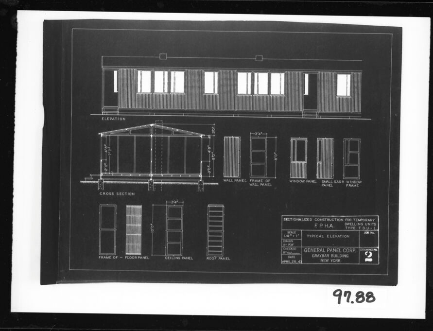
This image shows a black and white architectural drawing or blueprint of a building. The various views provided include an elevation, cross-section, and detailed drawings of building components such as wall panels, window panels, and a sash window frame. The drawing is detailed and contains measurements and notes on the construction. There is a label at the bottom right corner that reads "SECTIONALIZED CONSTRUCTION FOR TEMPORARY F. H. A. TYPE UNITS", indicating that these plans may be for temporary housing units as a part of the Federal Housing Administration (FHA) projects. There's also a mention of "GENERAL PANEL CORP. GRAYBAR BUILDING, NEW YORK". The drawing number or code "91.88" is visible at the bottom. The architectural plans are neatly organized, and the drafting style suggests that it may be from the mid-20th century, a common period for FHA type constructions. The clarity and precision in the drawing suggest it was meant for professional use, likely by architects, builders, or engineers involved in the construction of the depicted building.
Created by gpt-4o-2024-05-13 on 2024-12-07
The image appears to be an architectural blueprint of a sectionalized construction for temporary dwelling units. Details about the layout and design are printed on a dark background with white lines and text, typical of engineering drawings. The blueprint includes the following sections: 1. **Elevation View**: This shows the side view of the temporary dwelling unit. It includes details such as windows, door placement, and overall exterior appearance. 2. **Cross Section View**: This shows a vertical cut-through of the building, providing details on the internal structure, including floor, wall, and roof construction. 3. **Panels and Frames**: There are detailed drawings of various components such as: - Wall Panel - Frame of Wall Panel - Window Panel - Small Sash Window Frame - Roof Panel - Floor Panel - Ceiling Panel 4. **Label Information**: At the bottom right, there is a label with various details: - Title: Sectionalized Construction for Temporary Dwelling Units - Organization: F.P.H.A. (likely an acronym related to housing or public housing administration) - Scale: 1/4 inch = 1 foot - Dimensions - Date: April 29, 1941 - Company: General Panel Corp., Graybar Building, New York The blueprint number "97.88" is written in the bottom right corner outside the main drawing area.
Anthropic Claude
Created by claude-3-haiku-20240307 on 2024-12-07
The image shows a technical drawing or blueprint for a modular building or temporary dwelling unit. It includes detailed cross-sections, elevations, and component specifications such as wall panels, window frames, and roof panels. The drawing appears to be labeled "GENERAL PANEL CORP., BEAVER BUILDING, NEW YORK" and is dated April 29, 1957. The overall design and construction details suggest this is an architectural or engineering drawing for a prefabricated or modular housing solution.
Created by claude-3-5-sonnet-20241022 on 2024-12-07
This is an architectural blueprint or technical drawing showing details for a sectionalized construction of temporary housing units for the FPHA (Federal Public Housing Authority). The drawing includes multiple views: 1. An elevation view showing a rectangular building with multiple windows and vertical siding 2. A cross-section showing the roof truss system and internal structure 3. Several detailed drawings of construction components including: - Wall panel frame - Window panel - Floor panel - Ceiling panel - Roof panel The drawing appears to be from the General Panel Corporation in New York and is labeled as drawing number 2. It's rendered as a negative image (white lines on dark background) which was a common format for architectural blueprints. The drawing is dated and includes scale measurements and dimensional details for the various building components. The number "97.88" appears to be an archival or reference number in the bottom right corner.
Meta Llama
Created by us.meta.llama3-2-11b-instruct-v1:0 on 2024-12-07
The image presents a technical drawing of a building's elevation and cross-section, showcasing its architectural design. The drawing is rendered in white on a black background, with a white border surrounding it. * **Elevation Drawing** * The elevation drawing depicts the front view of the building. * It features a series of windows along the top, accompanied by a wall panel below. * The drawing includes labels for various components, such as the "ELEVATION," "WALL PANEL," "FRAME OF WALL PANEL," "WINDOW PANEL," "SMALL SASH WINDOW PANEL," and "FRAME." * **Cross-Section Drawing** * The cross-section drawing illustrates the building's side view. * It shows the frame of the floor panel, ceiling panel, roof panel, and wall panel. * The drawing includes labels for these components, providing a detailed understanding of the building's structure. * **Additional Information** * In the bottom-right corner, the drawing includes additional information about the construction project. * This section provides details on the scale, layout, and typical elevation of the building. * It also mentions the general panel corp., graybar building, new york, and the date of the drawing, which is april 28, 1938. * **Background and Border** * The drawing is set against a black background, which provides a clear contrast to the white lines and text. * A white border surrounds the drawing, adding a touch of elegance to the overall design. In summary, the image presents a detailed technical drawing of a building's elevation and cross-section, highlighting its architectural features and providing valuable information about the construction project.
Created by us.meta.llama3-2-90b-instruct-v1:0 on 2024-12-07
The image presents a detailed architectural drawing of a building, showcasing its elevation and cross-section. The drawing is rendered in white on a black background, with a white border surrounding it. The building's design features a flat roof and a rectangular shape, comprising two stories. The first floor boasts a covered porch, while the second floor has a balcony. The elevation view displays the building's front facade, highlighting the placement of windows and doors. The cross-section view provides a cutaway perspective, revealing the internal structure and layout of the building. Notably, the drawing includes labels and measurements, offering a comprehensive understanding of the building's design and construction. In the bottom-right corner, a small box contains information about the drawing, including the scale, date, and title. The title reads "SECTIONALIZED CONSTRUCTION FOR TEMPORARY F.P.H.A. DWELLING UNITS TYPE 1-D-2," indicating that the building is designed for temporary housing purposes. The scale is listed as 1/4" = 1'-0," and the date is April 28, 1944. Additionally, the box includes the name of the company responsible for the drawing, Graybar Building, New York. Overall, the image provides a detailed and informative representation of the building's design and construction, making it a valuable resource for architects, engineers, and builders.
Amazon Nova
Created by amazon.nova-lite-v1:0 on 2025-02-27
This image is a blueprint or architectural drawing of a building. It appears to be a plan or elevation view of the building, showing the layout and dimensions of the structure. The drawing includes various sections and labels, such as "WALL PANEL," "FRAME OF WALL PANEL," "WINDOW PANEL," "SMALL SASH WINDOW PANEL," and "FRAME." The drawing also includes a cross-section view of the building, which shows the interior layout and structural details. The drawing is labeled with the date "APRIL 28, 1968" and the location "GRAYBAR BUILDING, NEW YORK." The drawing is numbered "97.88" and appears to be a part of a larger set of drawings or plans for the building.
Created by amazon.nova-pro-v1:0 on 2025-02-27
The image is a blueprint of a structure with a black border and a black background. The blueprint is divided into two sections. The upper section shows a top view of the structure, while the lower section shows a side view of the structure. The blueprint also includes a cross-section of the structure, which shows the different parts of the structure, such as the wall panel, window panel, and roof panel. The blueprint also includes a scale and a drawing number.
Text analysis
Amazon