Machine Generated Data
Tags
Color Analysis
Feature analysis
Amazon
| Monitor | 95.9% | |
Categories
Imagga
| text visuals | 99.9% | |
Captions
Microsoft
created on 2022-06-04
| a flat screen tv sitting on top of a desk | 48.9% | |
| a flat screen tv sitting on top of a table | 41.4% | |
| a flat screen tv | 41.3% | |
OpenAI GPT
Created by gpt-4 on 2024-12-08
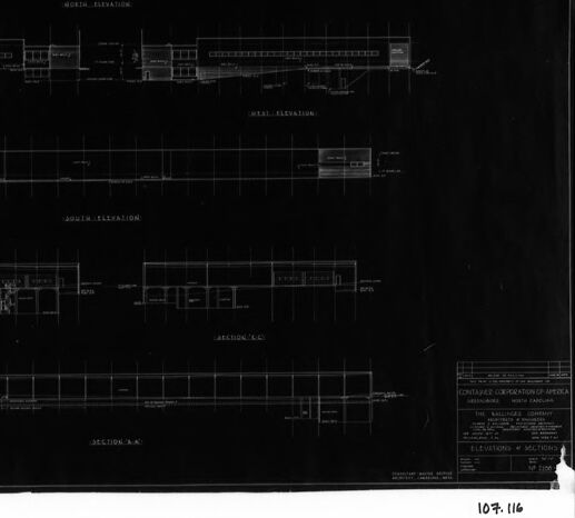
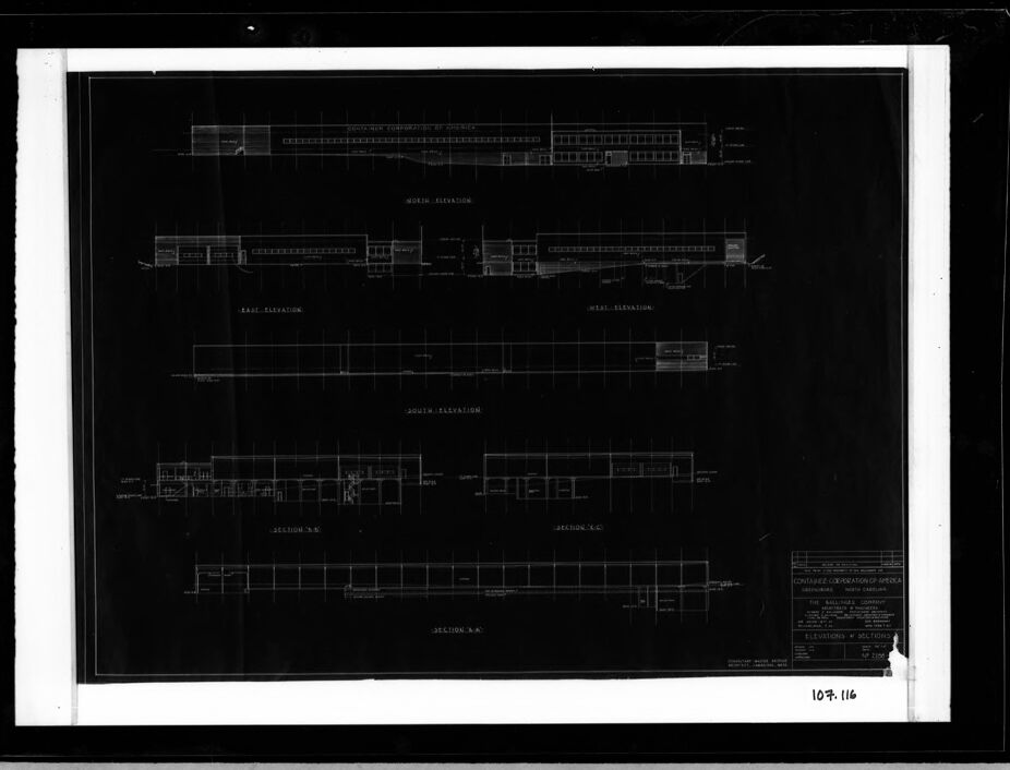
The image depicts an architectural drawing or blueprint featuring various elevations and sections of a structure. This technical drawing includes front, side, and cross-sectional views, providing details about the dimensions and layout of the building's components. The drawing is presented in white lines and text on a dark background, which is typical for the negative of a blueprint or a photocopy negative of a drawing. To the bottom right, there's a title block with text that appears to include information about the drawing, such as the project title, drawing title, the scale used, the name of the architect or firm, and possibly dates and other pertinent details. However, the specific text on the title block is illegible in this image. The image has a dark border around the perimeter of the drawing, suggesting it might have been photographed or scanned with a background. At the very bottom of the image, handwritten or printed numbers "1072.116" can be seen, which could correspond to a filing or cataloging system used for architectural or engineering drawings.
Created by gpt-4o-2024-05-13 on 2024-12-08
This image depicts an architectural blueprint that appears to show various elevations and sections of a building. The blueprint is presented on a dark background with fine white lines and text indicating different views of the building: - **Top Section:** Labeled "North Elevation," it shows a detailed view of the northern side of the building. - **Second Section:** Labeled "East Elevation," it displays the eastern side of the building. - **Third Section:** Labeled "South Elevation," it illustrates the southern side. - **Bottom Sections:** These are labeled as "Section A-A" and "Section B-B," representing cross-sectional views of the building’s interior structure. Each section includes annotations and measurements likely detailing dimensions, structural components, and materials. The bottom right corner contains a legend or key with additional specifics about the drawing, such as the title, scale, project details, and possibly the architect or engineering firm involved. The entire blueprint is framed or mounted for display or preservation, as noted by the surrounding white border and dark frame.
Anthropic Claude
Created by claude-3-haiku-20240307 on 2024-12-08
The image appears to be an architectural blueprint or technical drawing depicting the elevations and sections of a building design. The drawing shows various views and cross-sections of the structure, including the north, east, and south elevations, as well as section views. The image is presented in a high-contrast black and white format, typical of technical drawings and blueprints.
Created by claude-3-5-sonnet-20241022 on 2024-12-08
This image appears to be an architectural blueprint or technical drawing showing various elevations and sections of a building. The drawing is in a traditional architectural style with white lines on a dark background (likely a blueprint reproduction). It shows multiple views including north, south, east, and west elevations, as well as several cross-sectional views labeled as "SECTION A-A," "SECTION B-B," etc. The drawings appear to be for a low-rise commercial or institutional building with horizontal emphasis in its design. The drawings include details of the building's exterior features, height variations, and structural elements. This is presented in a formal architectural documentation format with proper labeling and scaling typical of professional architectural drawings.
Meta Llama
Created by us.meta.llama3-2-11b-instruct-v1:0 on 2024-12-08
The image presents a black-and-white blueprint, which appears to be a technical drawing or architectural plan. The blueprint is framed by a thick white border, surrounded by a black border, and features a light gray background. The blueprint itself is predominantly black, with white lines and text used to convey information. **Key Features:** * **Border:** The blueprint is framed by a thick white border, which is surrounded by a black border. * **Background:** The background of the blueprint is light gray. * **Blueprint:** The blueprint itself is predominantly black, with white lines and text used to convey information. * **Text and Lines:** The blueprint features various lines and text, including labels, measurements, and other technical details. * **Numbering:** In the bottom-right corner of the blueprint, the number "107.116" is handwritten in black ink. **Overall Impression:** The image suggests that the blueprint is a technical drawing or architectural plan, possibly for a building or structure. The level of detail and precision in the blueprint indicates that it is a professional document, likely created by an architect or engineer. The presence of the number "107.116" in the bottom-right corner of the blueprint may indicate that it is part of a larger set of plans or documents.
Created by us.meta.llama3-2-90b-instruct-v1:0 on 2024-12-08
This image presents a black-and-white architectural drawing of a building, likely created for construction purposes. The drawing is set against a black background and features white lines that outline the structure's various components. The drawing includes several sections, each labeled with its corresponding elevation (north, east, south, and west) and section (A-A and B-B). These labels provide context for understanding the different perspectives of the building. In the bottom-right corner of the drawing, a small section contains illegible text, which may include information about the building's design, materials, or other relevant details. Unfortunately, the text is too small to decipher. The drawing is surrounded by a white border, which adds a touch of contrast to the overall design. The border also helps to frame the image and create a sense of depth. Overall, this image provides a detailed and informative representation of a building's architecture, making it a valuable resource for architects, engineers, and construction professionals.
Amazon Nova
Created by amazon.nova-lite-v1:0 on 2025-02-26
The image appears to be a technical drawing or blueprint of a building or structure. It consists of several sections, each showing different elevations or views of the building. The drawing is in black and white and has a grid-like pattern, indicating that it is a scaled representation. The top section of the drawing shows the north elevation of the building, while the bottom section shows the south elevation. In between, there are two other sections that likely represent different views or sections of the building. The drawing includes labels and annotations, such as "NORTH ELEVATION," "SOUTH ELEVATION," and "SECTION A-A," which help to identify the different parts of the building and provide context for the viewer. Overall, the image appears to be a detailed and technical representation of a building or structure, intended for use by architects, engineers, or construction professionals.
Created by amazon.nova-pro-v1:0 on 2025-02-26
The image is a technical drawing or blueprint of a structure, possibly a building or a part of a construction project. The drawing is in black and white, and it is framed by a black border. The blueprint is divided into several sections, each labeled with different names and elevations, such as "North Elevation," "South Elevation," and "Section A-A." Each section shows a different view of the structure, with lines and measurements indicating the dimensions and layout. There is also a table on the right side of the blueprint that lists various details about the structure, such as the materials used, the dimensions of different parts, and other relevant information. The overall impression is that this is a detailed and precise technical drawing used for construction or engineering purposes.
Text analysis
Amazon