Machine Generated Data
Tags
Color Analysis
Feature analysis
Amazon
Clarifai
AWS Rekognition
| Monitor | 91.5% | |

Categories
Imagga
created on 2022-06-04
| interior objects | 69.9% | |
| text visuals | 23.7% | |
| streetview architecture | 4% | |
Captions
Microsoft
created by unknown on 2022-06-04
| a blackboard sign on a wall | 78.2% | |
| a blackboard near a monitor | 74.1% | |
| a close up of a blackboard | 74% | |
Clarifai
No captions written
Salesforce
Created by general-english-image-caption-blip on 2025-05-15
a photograph of a black and white photo of a black and white picture of a diagram of a
Created by general-english-image-caption-blip-2 on 2025-06-28
a black and white photo of a blueprint of a building
OpenAI GPT
Created by gpt-4 on 2024-12-07
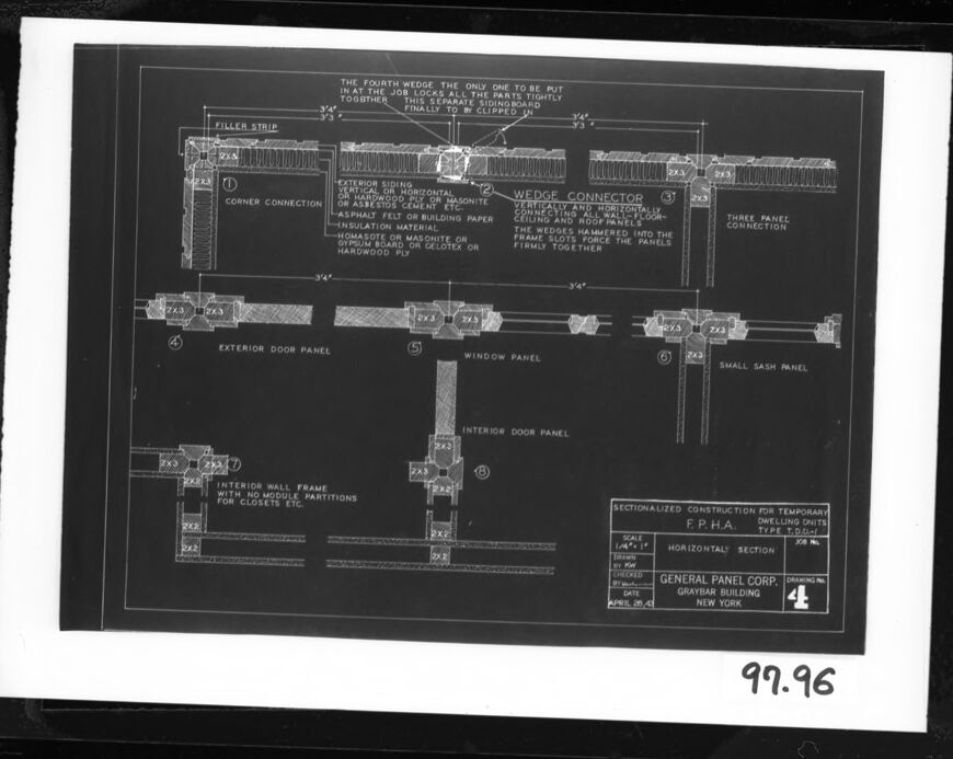
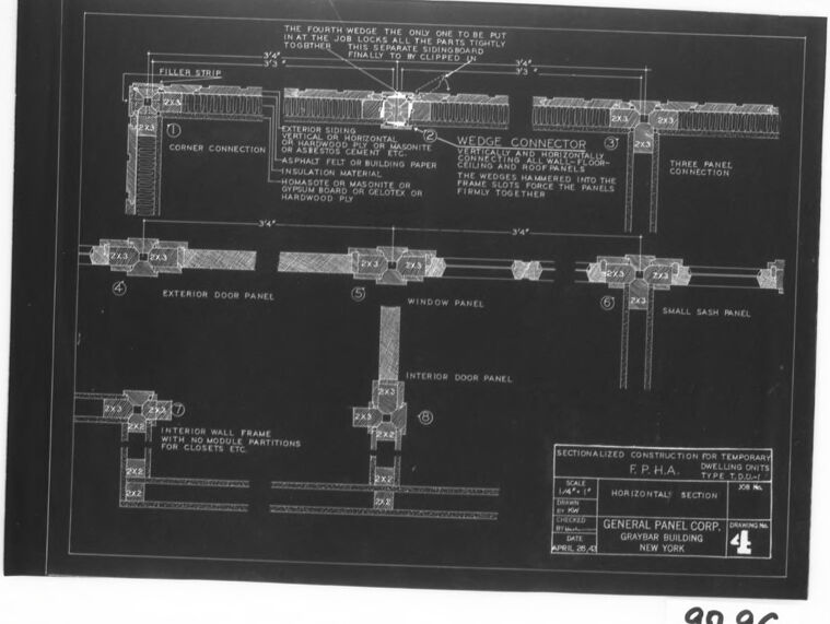
This image displays a framed architectural drawing or blueprint, viewed in negative, where white lines and text appear on a dark background. It appears to be a detailed construction plan showing sectional views of specific building elements like a door, window, and wall panels. These are labeled as an "EXTERIOR DOOR PANEL," "WINDOW PANEL," "INTERIOR DOOR PANEL," and "INTERIOR WALL FRAME FOR DEMOUNTABLE PARTITIONS." Additionally, details include "WEDGE CONNECTOR," "THREE PANEL CONNECTION," and other construction notes.
The sections also depict various layers within these constructions, such as insulation, framing, and hardware placement. On the bottom right, there's text that says "SECTIONALIZED CONSTRUCTION FOR TEMPORARY DWELLING UNITS," which implies that the construction is meant for temporary structures. The document is marked with a scale (1/2" = 1'-0"), reference to the General Panel Corp., Graysler Building, New York, and has a figure number or reference "4" at the bottom. It's important to note that since the image is a negative, the original document would display dark lines and text on a white background. The number "99.96" is also visible, likely a catalog or archival reference.
Created by gpt-4o-2024-05-13 on 2024-12-07
This image appears to be a technical drawing or blueprint. It includes detailed diagrams of panel connections, with annotations indicating various sections and specific details about the construction components.
Key elements include:
- Filler Strip: Detailed near the "Corner Connection."
- Wedge Connector: Described for use in securely connecting panels, with specific mentions of the materials and fitting process.
- Exterior Door Panel: Sectioned and detailed with measurements.
- Window Panel: Includes small panel and sash details.
- Interior Wall Frame: Specific for use in module partitions, such as closets.
Additional labels include:
- "Three Panel Connection"
- "Small Sash Panel"
- "Horizontal Section"
At the bottom right:
- Title: "SECTIONALIZED CONSTRUCTION FOR TEMPORARY DWELLING UNITS"
- Organization: "General Panel Corp., Graybar Building, New York"
- Drawing No: "4E"
- Date: "April 25, 1943"
On the lower right corner outside the main frame:
- A handwritten note "99.96"
The drawing is highly detailed, likely meant for reference in construction or engineering contexts.
Anthropic Claude
Created by us.anthropic.claude-3-5-sonnet-20241022-v2:0 on 2025-06-24
This is an architectural or engineering blueprint/technical drawing showing detailed cross-sectional views of various panel construction elements. The drawing appears to be from the General Panel Corporation in New York for the Graybar Building. It shows specifications for different types of panels including exterior door panels, window panels, small sash panels, and interior wall frames. The drawing includes detailed measurements and notes about construction methods, including information about wedge connectors and panel assembly. The drawing is done in white lines on a dark background, which is typical of blueprint style technical drawings. At the top, there's a note about "THE FOURTH WEDGE" being the only one to be put in a certain way. The drawing is labeled as a "SECTIONALIZED CONSTRUCTION FOR TEMPORARY E.P.H.A." and appears to be drawing number 4 in a series.
Created by claude-3-haiku-20240307 on 2024-12-07
The image appears to be a technical diagram or architectural drawing. It shows detailed schematics and specifications for various components of a building, including exterior door panels, window panels, and interior wall frames. The drawing is detailed and appears to be an engineering or construction plan for a specific project, as indicated by the annotations and labels throughout the image.
Created by claude-3-5-sonnet-20241022 on 2024-12-07
This is a technical architectural blueprint or construction drawing showing various panel and connection details. The drawing appears to be from the General Panel Corporation in New York for what's labeled as the Graybar Building. It shows detailed cross-sectional views of different panel assemblies including exterior door panels, window panels, interior door panels, and wall frame components. The drawing includes specific measurements and annotations about construction methods, particularly focusing on wedge connectors and panel joints. There's a note about "THE FOURTH WEDGE" at the top of the drawing. The document appears to be a professional architectural or engineering document, drawn in white lines on a dark background, typical of blueprint style technical drawings from the mid-20th century. The number "99.96" is visible in the corner of the photograph.
Meta Llama
Created by us.meta.llama3-2-11b-instruct-v1:0 on 2024-12-07
The image depicts a technical drawing of a building's interior and exterior walls, showcasing the various components that make up the structure. The drawing is presented on a black background with white lines and text, providing a clear visual representation of the building's design.
Key Features:
- Exterior Walls: The drawing highlights the exterior walls, which are composed of multiple layers, including a filler strip, corner connection, wedge connector, and three-panel connection.
- Interior Walls: The interior walls are also depicted, featuring a window panel, interior door panel, and small sash panel.
- Window Panel: The window panel is shown as a separate entity, with its own dimensions and specifications.
- Door Panels: The door panels are illustrated as part of the interior walls, with their own dimensions and connections to the surrounding walls.
- Sash Panel: The sash panel is depicted as a small, rectangular component attached to the interior wall.
- Dimensions: The drawing includes various dimensions and measurements, such as the width and height of each component, as well as the spacing between them.
- Labels: Each component is labeled with its corresponding name, making it easy to identify and understand the different parts of the building's structure.
- Scale: The drawing is scaled to 1/4 inch = 1 foot, allowing for accurate measurements and calculations.
- Date: The drawing is dated April 25, 1945, indicating when it was created.
- Company: The drawing is attributed to General Panel Corp., Graybar Building, New York, suggesting that it was created by a company specializing in panel construction.
Overall:
The technical drawing provides a detailed and accurate representation of the building's interior and exterior walls, highlighting the various components that make up the structure. The use of clear labels, dimensions, and measurements ensures that the drawing is easy to understand and interpret, making it a valuable resource for architects, engineers, and builders.
Created by us.meta.llama3-2-90b-instruct-v1:0 on 2024-12-07
The image is a black-and-white technical drawing of a building's wall section, featuring various components such as windows, doors, and panels. The drawing is labeled with numbers and text, providing detailed information about the construction process. The image appears to be a historical document, likely from the mid-20th century, given its age and the style of the drawing. The presence of a date stamp in the bottom-right corner suggests that the image was created or archived on April 20, 1943. Overall, the image provides valuable insight into the design and construction techniques used during this time period.
Amazon Nova
Created by amazon.nova-lite-v1:0 on 2025-02-27
This image appears to be a technical drawing or blueprint related to construction or building design. It shows various panels, connections, and measurements. Here's a detailed description:
The image is a black-and-white technical drawing with a black border. It depicts a construction or building design with various panels and connections.
At the top, there is a label that reads "SECTIONALIZED CONSTRUCTION FOR TEMPORARY DWELLING UNITS TYPE T.P.H.A." This suggests that the drawing is related to the construction of temporary housing units for a specific type of housing program.
The drawing includes several panels and connections, including:
- Exterior siding
- Corner connection
- Wedge connector
- Three-panel connection
- Exterior door panel
- Window panel
- Small sash panel
- Interior door panel
- Interior wall frame with no module partitions for closets, etc.
The drawing also includes measurements and dimensions for the various panels and connections. For example, there are measurements for the exterior siding, corner connection, wedge connector, and other components.
Overall, the image appears to be a technical drawing or blueprint related to the construction of temporary housing units, likely for a specific housing program or initiative. The drawing provides detailed information about the panels, connections, and dimensions required for the construction of these units.
Created by amazon.nova-pro-v1:0 on 2025-02-27
The image is a detailed architectural blueprint or construction plan for a building, specifically focusing on the exterior wall and door panel sections. The blueprint is presented on a black background with white text and lines, which is typical for such documents to ensure clarity and precision. The plan includes several key components and annotations:
Exterior Wall Frame: This section of the blueprint details the structure of the exterior wall, including dimensions and materials. It mentions "INTERIOR WALL FRAME WITH NO MODULE PARTITIONS FOR CLOSETS ETC," indicating that the wall frame does not include internal partitions for closets.
Exterior Door Panel: The blueprint outlines the construction of the exterior door panel, specifying materials and dimensions. It includes a section labeled "INTERIOR DOOR PANEL," suggesting that the door panel design is consistent with the interior door design.
Wedge Connector: This part of the blueprint describes the "WEDGE CONNECTOR," which is used to secure and connect different sections of the wall or door panel. It mentions "VERTICALLY AND HORIZONTALLY," indicating the orientation of the wedge connector.
Corner Connection: The blueprint details the "CORNER CONNECTION," which is crucial for joining wall sections at corners. It specifies the use of "EXTERIOR SIDING OR HARDWOOD MASONITE OR ASBESTOS CEMENT ETC," suggesting various materials that can be used for this connection.
Filler Strip: This component is used to fill gaps or spaces between wall sections or panels. The blueprint indicates the dimensions and placement of the filler strip.
Sectionalized Construction for Temporary Dwelling Units: The blueprint includes a section labeled "SECTIONALIZED CONSTRUCTION FOR TEMPORARY DWELLING UNITS," which suggests that the design is adaptable for temporary housing solutions.
General Panel Corp. Information: At the bottom of the blueprint, there is a reference to "GENERAL PANEL CORP. GRAYBAR BUILDING NEW YORK," along with a date "APRIL 26-45," indicating the company responsible for the design and the date of the blueprint.
Scale and Dimensions: The blueprint includes a scale of "1/4" = 1'-0"" and mentions "HORIZONTAL SECTION," providing context for the dimensions and layout of the components.
Annotations and Notes: Various annotations and notes are scattered throughout the blueprint, providing additional details and instructions for the construction process.
In summary, the blueprint is a comprehensive guide for constructing exterior walls and door panels, with detailed specifications for materials, dimensions, and construction techniques. It is designed for temporary dwelling units and includes annotations and notes to ensure accurate implementation.
Google Gemini
Created by gemini-2.0-flash-lite on 2025-04-28
Here's a description of the image:
Overview:
The image is a black and white blueprint or architectural drawing. It appears to be a sectional view, likely detailing a construction method or design for temporary housing units.
Specific Elements:
- Title/Purpose: The drawing's purpose is "SECTIONALIZED CONSTRUCTION FOR TEMPORARY DWELLING UNITS". It specifies the "F.P.H.A." (likely a housing authority or agency) and "TYPE T.D.U." (presumably a model or type designation).
- Components: The drawing illustrates various components:
- Corner Connection: Details how exterior siding is joined at a corner.
- Wedge Connector: Shows how panel sections are connected using wedges.
- Panel Connections: Shows three types of connections to other structural elements.
- Exterior Door Panel: Details the design of an exterior door.
- Window Panel: Illustrates a window within the wall structure.
- Small Sash Panel: Illustrates the detail of a small sash panel.
- Interior Wall Frame: Shows the framing for an interior wall, possibly with spaces for closets.
- Materials: The diagram lists various materials used in construction, including:
- Exterior siding (vertical or horizontal).
- Hardwood ply or Masonite.
- Asphalt felt or building paper.
- Insulation material.
- Homosote or Masonite or gypsum board.
- Layout and Structure: The drawing is a sectional view, breaking down the various structural elements and how they connect. It includes dimensions (e.g., 3'4") and labels to identify the different components.
- Scale and Details: The scale is 1/4" = 1" (meaning ¼ inch on the drawing represents 1 inch in the real-world structure). The sections provide a breakdown of how the elements fit together.
- Labels and Text: The blueprint has many labels and text annotations to describe the elements and their function.
- General Panel Corp.: It indicates that the design was produced by "GENERAL PANEL CORP." located in the Graybar Building, New York.
Overall Impression:
The image is a professional drawing, likely used for construction, documenting a specific design for temporary housing units. It shows technical details about construction.
Created by gemini-2.0-flash on 2025-04-28
Here is a description of the image:
The image is a black-and-white architectural blueprint drawing. It depicts sectional details for the construction of temporary dwelling units. The drawing is titled "SECTIONALIZED CONSTRUCTION FOR TEMPORARY DWELLING UNITS," and is attributed to the F.P.H.A. with type T.D.U.-1. The scale is 1/4" = 1', and it is a horizontal section. It was drawn by K.W., checked by H.G., and dated April 26, 1943.
The drawing includes details of various parts, such as a corner connection (labeled 1), a wedge connector (labeled 2), and a three-panel connection (labeled 3). It also shows exterior and interior door panels (labeled 4 and 8, respectively), a window panel (labeled 5), a small sash panel (labeled 6), and an interior wall frame (labeled 7).
Text notes describe materials such as exterior siding (vertical or horizontal, redwood plywood or masonite or asbestos cement), asphalt felt or building paper, and insulation material. It is labeled with the text "97.96" near the bottom of the image.
The company listed is General Panel Corp. Graybar Building, New York, and it is drawing number 4.
Mistral Pixtral
Created by us.mistral.pixtral-large-2502-v1:0 on 2025-04-28
The image is a detailed architectural drawing that outlines the construction method for a panelized building system. The drawing appears to be from the General Panel Corporation, located in the Graybar Building, New York. Here is a breakdown of the components illustrated in the drawing:
Corner Connection: This section shows how the exterior siding (which can be made of wood, hardboard, plywood, asbestos cement, etc.) is connected at the corner of the building. It includes insulation material and a gypsum board or plaster on the interior.
Wedge Connector: This part demonstrates the method for joining horizontal panels. The wedges are hammered in to securely fasten the panels together.
Three Panel Connection: This section illustrates how three panels are connected together, likely at an intersection or corner.
Exterior Door Panel: Shows the construction details for an exterior door, including the framing and connection points.
Window Panel: Depicts the framing and installation details for a window within the panel system.
Small Sash Panel: Illustrates a smaller panel, possibly for a smaller window or vent.
Interior Door Panel: Details the construction for an interior door within the panel system.
Interior Wall Frame for Partitions for Closets, etc.: Shows the framing for interior walls, which can be used for partitions or closets.
The drawing includes various measurements and material specifications, indicating the precise construction techniques and components required for assembling the building. The note at the top mentions that the foundation is the only part that needs to be put in, suggesting that the rest of the structure can be assembled using these prefabricated panels. The drawing is approved by the F.P.H.A. (Federal Public Housing Authority) for dwelling units under Section 207.
Overall, the image provides a comprehensive guide for constructing a panelized building, detailing the connections, framing, and installation of various components.
Qwen
Created by Qwen/Qwen2.5-VL-7B-Instruct on 2025-07-26
The image is a technical drawing or blueprint for a construction project, specifically related to the assembly and construction of panels for temporary dwellings. The drawing is labeled as "Sectionalized Construction for Temporary Dwelling Units" and is associated with F.P.H.A. (Federated Printers' Housing Authority). It is dated April 26, 1945 and is attributed to General Panel Corp., Graybar Building, New York.
The drawing details various components of the construction, including:
- Wedge Connector: A device used to connect panels together.
- Exterior Siding: The material used to cover the exterior of the panel.
- Filler Strip: A component used for joining different parts of the panel.
- Corner Connection: The way the panels are joined at corners.
- Insulation Material: Options for insulation such as Homasote, Masonite, Celotex, or hardwood.
- Window Panel: A section designed for window placements.
- Exterior Door Panel: A section for exterior doors.
- Interior Door Panel: A section for interior doors.
- Small Sash Panel: A section for smaller window or door panels.
- Interior Wall Frame: The frame used for internal walls with no module partitions for closets, etc.
The drawing also specifies measurements and construction techniques, such as hammering wedges into the frame to ensure the panels are firmly connected. The text at the top emphasizes the importance of a tight fit for the fourth wedge. The drawing provides a detailed guide for assembling the panels, ensuring they fit together properly for the construction of temporary dwellings.
Created by Qwen/Qwen2.5-VL-72B-Instruct on 2025-07-26
This image is a technical blueprint or architectural drawing detailing the construction of modular sections for a temporary dwelling unit. The blueprint is labeled "Sectionalized Construction for Temporary Dwelling Units" and is associated with the FPHA (Federal Public Housing Authority). It is dated April 26, 1943, and was produced by the General Panel Corp. in New York.
The drawing is divided into several sections, each illustrating different components of the modular construction:
- Corner Connection: This section shows how the exterior siding and corner connections are made, with a focus on the wedge connector system.
- Wedge Connector: The blueprint provides a detailed view of the wedge connector used to secure the panels together.
- Three Panel Connection: This section illustrates how three panels are connected using the wedge system.
- Exterior Door Panel: This part shows the construction of the exterior door panel, including the framing and door placement.
- Window Panel: The window panel is depicted with its framing and window placement.
- Small Sash Panel: This section details the construction of a small sash panel.
- Interior Door Panel: The interior door panel is shown with its framing and door placement.
- Interior Wall Frame with No Module Partitions for Closets etc.: This section illustrates the interior wall frame and how it is constructed without partitions for closets.
Each section includes detailed annotations and specifications, such as the dimensions of the panels and the materials used. The drawing is meticulously labeled to ensure clarity in the construction process. The number "97.96" is written at the bottom right corner of the image, possibly indicating a reference or catalog number.
Text analysis
Amazon