Machine Generated Data
Tags
Color Analysis
Feature analysis
Amazon
Clarifai
AWS Rekognition
| Monitor | 88.5% | |


Categories
Imagga
created on 2022-06-04
| interior objects | 46% | |
| text visuals | 37.8% | |
| cars vehicles | 7.5% | |
| streetview architecture | 6.1% | |
| paintings art | 1.4% | |
Captions
Microsoft
created by unknown on 2022-06-04
| a screen shot of a computer | 59.7% | |
| a screen shot of a computer monitor | 39.7% | |
| a screen shot of a monitor | 39.6% | |
Clarifai
No captions written
Salesforce
Created by general-english-image-caption-blip on 2025-05-21
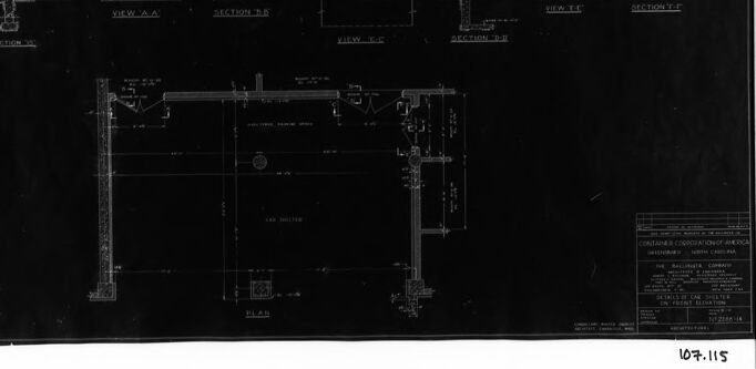
a photograph of a black and white photo of a building with a black and white drawing of a
Created by general-english-image-caption-blip-2 on 2025-07-02
a black and white photo of a building with plans
OpenAI GPT
Created by gpt-4 on 2024-12-08
This image depicts a blueprint or technical drawing, which is traditionally created on a dark background with white lines. The drawing includes several views of what appear to be architectural or engineering plans, possibly for a structure or a component of a building.
The lower right corner contains a block of text, which typically includes information such as the title of the project, the scale used in the drawing, the name of the architect or engineer, the company involved, and other relevant details like the drawing number and date.
From the various views, which have labels like "SECTION AA," "VIEW AA," "SECTION BB," etc., it seems that there are different cross-sections and elevational views of a part of a building, possibly showcasing the design of windows, walls, or other structural elements. The precise, neat lines and annotations suggest professional architectural or engineering work.
Created by gpt-4o-2024-05-13 on 2024-12-08
This image depicts a technical architectural drawing or blueprint. The drawing is detailed with various views and sections of what appears to be door and wall structures. It includes measurements, notes, and labels that provide instructions and specifications for construction.
Key elements of the drawing include:
- Section Views: Cross-sectional depictions of walls and doors, showing the internal structure and materials.
- Elevation Views: External views of the doors and how they are positioned within the wall.
- Plan View: A horizontal view (layout) from above that shows the positioning and arrangement of various architectural elements.
- Annotations: Various notes and labels indicating measurements and construction details.
- Title Block: Located in the bottom right corner, this block likely contains information about the project, such as the project name, firm or architect, date, and relevant codes or standards.
The dark background with white lines and text suggests that this is an older style blueprint, traditionally used before modern computer-aided design (CAD) became prevalent.
Anthropic Claude
Created by claude-3-haiku-20240307 on 2024-12-08
The image appears to be an architectural blueprint or technical drawing. It shows various views and cross-sections of a structure, likely a building or a part of a building. The drawing includes detailed technical specifications and measurements, suggesting this is an engineering or construction document.
Created by claude-3-5-sonnet-20241022 on 2024-12-08
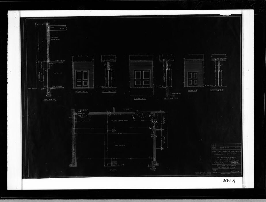
This appears to be an architectural blueprint or technical drawing, shown as a negative image (white lines on black background). The drawing shows multiple views and sections of what seems to be window or door details. At the top of the image, there are several elevation views showing double-door or window units with their corresponding sectional details. The bottom portion of the drawing contains what appears to be a plan view or larger sectional detail. The drawing includes various dimensional notations and construction details typical of architectural drawings. The image has a frame or border around it and appears to be a historical or archived document, given its style and presentation.
Created by us.anthropic.claude-3-5-sonnet-20241022-v2:0 on 2025-06-26
This appears to be an architectural blueprint or technical drawing showing various door and window details. The image is a black and white negative (white lines on black background) showing multiple views including elevations and sections of what appears to be door or window installations. At the top of the drawing, there are several repeated elevation views showing double-door or window units with their corresponding sectional details. The bottom portion of the drawing shows what appears to be a plan view or larger sectional detail. The drawing includes various technical notations and dimension lines typical of architectural drawings. The document appears to be professionally drafted and likely dates from an era when blueprints were hand-drawn rather than computer-generated.
Meta Llama
Created by us.meta.llama3-2-11b-instruct-v1:0 on 2024-12-08
The image depicts a black-and-white blueprint for a building, featuring a white border and a black background. The blueprint is divided into sections, with each section labeled and containing detailed architectural drawings of windows, doors, and other structural elements. The overall design appears to be a floor plan or elevation of a building, showcasing the layout and features of the structure.
The blueprint is likely used for construction or renovation purposes, providing a precise and detailed representation of the building's design and layout. The use of a black background and white lines creates a clear and legible visual representation of the building's architecture, making it easier to understand and interpret the design.
Created by us.meta.llama3-2-90b-instruct-v1:0 on 2024-12-08
This image is a black and white architectural blueprint, featuring a floor plan with multiple sections. The blueprint is presented in landscape orientation, with a white border around the edges and a black background. The floor plan is divided into several sections, each labeled with a letter (A, B, C, etc.) and accompanied by a corresponding section view. The section views are depicted in a smaller scale, providing a detailed look at the architectural features of each section.
In the bottom-right corner of the blueprint, there is a small box containing text that appears to be a key or legend. The text is too small to read, but it likely explains the symbols and abbreviations used throughout the blueprint. The overall design of the blueprint suggests that it was created for a specific building or structure, possibly a residential or commercial property. The level of detail and precision in the blueprint indicates that it was intended for use by architects, engineers, or contractors during the construction process.
Amazon Nova
Created by amazon.nova-lite-v1:0 on 2025-02-25
The image is a technical drawing, likely an architectural or engineering blueprint. The drawing is presented in black and white, with a grid-like pattern in the background, suggesting a detailed and precise representation. The drawing contains several labeled sections, including "VIEW A-A," "SECTION A-A," "VIEW T-T," and "SECTION T-T," indicating different perspectives and cross-sections of the structure being depicted. The drawing also includes dimensions and measurements, with numbers and letters indicating specific points and distances. The overall composition of the drawing suggests a complex structure with multiple components and levels.
Created by amazon.nova-pro-v1:0 on 2025-02-25
The image is a black and white architectural blueprint of a building. The blueprint is divided into several sections, each labeled with a different view and section. The top section of the blueprint shows a series of elevations with windows and doors, while the bottom section shows a floor plan with dimensions and annotations. The blueprint also includes a title block with the name of the architect and the date of the drawing.
Google Gemini
Created by gemini-2.0-flash on 2025-05-18
Here is a description of the image:
The image is a black and white photograph of what appears to be an architectural blueprint or technical drawing. The drawing is set against a dark background, possibly the original photo negative or a scan that captured the surrounding frame. The drawing itself consists of several views, sections, and a plan of a structure.
At the top of the drawing, there are several sections, including "VIEW A A", "SECTION B B", "VIEW T T", and "SECTION T-P". These sections show a detailed look at the structure from various angles. In the center, there is a "PLAN" view, which offers a top-down perspective of the structure. The drawing contains fine lines and details, indicative of technical drafting or engineering.
At the bottom right corner, there is a small rectangular area with some text, likely containing the name of the project, the company, and the date of the drawing. Below this is a number, "107.115".
Created by gemini-2.0-flash-lite on 2025-05-18
Here's a description of the image:
Overall:
The image is a black and white architectural blueprint, or possibly a photostat of one. It appears to be a technical drawing, likely of a building facade and its details. The drawing is framed in a thick black border with a white matte.
Content:
- Elevations and Sections: The top portion of the blueprint depicts multiple elevations and sections of what seems to be a building's facade. These drawings show the design of the windows and surrounding structures.
- Plan View: The bottom part of the image is a plan view, perhaps a top-down representation of a section of the building. This section might include details about the layout, such as wall placements.
- Labels and Annotations: Various labels and annotations are present to identify different sections, views (e.g., "View A-A," "View E-E"), and potentially materials or dimensions.
Style and Medium:
- Blueprint Style: The use of black lines on a white or slightly toned background is typical of blueprints.
- Precision: The lines are drawn with precision, characteristic of architectural drawings.
- Overall, the drawing is intended for construction, or record documentation purposes.
Additional elements:
- On the lower right-hand corner is a title block with the company name and the number "107.115".
Mistral Pixtral
Created by us.mistral.pixtral-large-2502-v1:0 on 2025-06-05
The image is a black-and-white architectural drawing, likely a blueprint, showing detailed plans for a specific structure or part of a building. The drawing includes multiple views and sections of what appears to be a door frame or entrance assembly. Here are the key components visible in the drawing:
- Section A-A: A vertical cross-section view of the structure, showing internal components and dimensions.
- View A: A front elevation view of the door frame or entrance, displaying the outer appearance and dimensions.
- Section B-B: Another vertical cross-section view, possibly from a different angle or part of the structure.
- View B: Another front elevation view, similar to View A but potentially showing a different aspect or detail.
- Section C-C: A third vertical cross-section view, providing additional internal details.
- View C: A third front elevation view, complementing the previous views with more information.
- Detailed Plan View: A larger, more comprehensive plan view that includes additional structural elements and possibly the surrounding context.
The drawing includes various annotations, dimensions, and labels that provide specific measurements and descriptions of the components. The bottom right corner of the drawing has a legend or key that likely explains symbols, materials, or other relevant information. The number "167-115" is visible at the bottom right, which could be a reference or identification number for the drawing.
Overall, the image provides a detailed technical representation of a door frame or entrance assembly, useful for construction or architectural purposes.
Qwen
Created by Qwen/Qwen2.5-VL-7B-Instruct on 2025-07-27
The image appears to be a technical drawing or blueprint, likely used in the construction or design of a building. The drawing includes several sections and views, possibly detailing the construction of a structure or a specific part of a building.
- Views and Sections: The drawing includes labeled sections and views, such as "View A-A," "Section B-B," and "Section C-C," indicating different perspectives of the same structure.
- Details: There are detailed drawings of individual components, such as what looks like a wall section and a door frame, along with dimensions and labels that provide specific information about the design.
- Plan: Below the sections, there is a labeled "Plan," which likely represents the floor plan or a top-down view of the structure.
- Annotations and Labels: The drawing includes various annotations, such as measurements and labels, which are common in architectural and engineering drawings to provide precise information about the design.
The overall style and layout suggest that this is a technical document intended for use in the design or construction phase of a project. The content appears to be technical in nature, focusing on architectural or engineering details.
Created by Qwen/Qwen2.5-VL-72B-Instruct on 2025-07-27
The image shows a black and white blueprint-style architectural or engineering drawing. It features several different views and sections of a structure, likely a building or a part of a building. The drawing includes:
- Sectional Views: There are multiple sectional views labeled as "SECTION A-A," "SECTION B-B," "SECTION C-C," and "SECTION D-D." These views show cross-sections of the structure, providing details about the internal layout and construction.
- Plan View: There is a plan view labeled "PLAN" at the bottom of the drawing, which shows the top-down layout of the structure.
- Details and Annotations: The drawing includes various lines, symbols, and text annotations that provide additional information about the structure's design and specifications.
The drawing is presented on a black background with white lines, making it a negative image of a typical blueprint. The bottom right corner has a label or identifier "107.115."
Text analysis
Amazon