Machine Generated Data
Tags
Color Analysis
Feature analysis
Amazon
Clarifai
AWS Rekognition
| Monitor | 88.2% | |

Categories
Imagga
created on 2022-06-04
| text visuals | 97.1% | |
| streetview architecture | 1.9% | |
Captions
Microsoft
created by unknown on 2022-06-04
| a screen shot of a computer | 76.8% | |
| a screen shot of a computer monitor | 58.7% | |
| a screen shot of a monitor | 58.6% | |
Clarifai
No captions written
Salesforce
Created by general-english-image-caption-blip on 2025-05-16
a photograph of a black and white photo of a black and white photo of a building
Created by general-english-image-caption-blip-2 on 2025-07-02
a black and white photo of a blueprint
OpenAI GPT
Created by gpt-4 on 2024-12-07
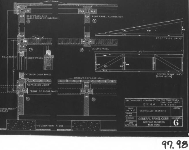
This is a black and white image of an architectural drawing or blueprint. The drawing shows various cross-sectional diagrams of parts of a building, illustrating how the different components are designed to fit together. For instance, there are detailed sections showing roofing, ceiling panels, a roof truss, an exterior door panel, expansion joints, and the foundation piers.
Each section has annotations and measurements detailing the dimensions, materials, and construction notes necessary for constructing the component it depicts, such as "ROOF PANEL AND GABLE TRUSS CONNECTION," "CEILING PANEL," and "FRAME OF FLOOR PANEL." The drawing incorporates various hatching patterns to represent different materials and installation guides, such as insulation board, fillers, and hardware flooring.
On the right side of the image, there's a small box providing information about the drawing itself, stating "SECTIONALIZED CONSTRUCTION FOR TEMPORARY & P.H.A. TYPE D.U.'S", with a scale noted as 1/4" = 1'-0" and the date March 24, 1942. The box also includes the name "GENERAL PANEL CORP." and "GENERATOR BUILDING" listed under the address for General Panel Corporation in New York.
There is a label or stamp in the bottom corner that reads "97.98," possibly indicating an inventory or catalog number associated with the print or drawing. The drawing is mounted on a board and framed with a mat for display or preservation.
Created by gpt-4o-2024-05-13 on 2024-12-07
The image is a black-and-white architectural blueprint titled "Sectionalized Construction for Temporary Dwelling Units" by the General Panel Corp., located in the Graybar Building, New York. The blueprint includes detailed construction sections and elements such as roof panel connections, roof trusses, ceiling panels, window panels, door panels, flooring, and foundation piers.
Some components and details visible in the blueprint include:
- Roof panel and gable truss connection
- Expansion joint
- Filler strip
- Window panel
- Exterior door panel
- Hardwood flooring
- Foundation piers
- Insulation board
Measurements and notes are annotated throughout the drawing, explaining the specifications of each section. At the bottom right, there's a notes section specifying the date, "April 2, 1943," along with instructions and approvals by F.P.H.A., Type L.D.10a, Vertically Sections.
The number "99.98" is handwritten at the bottom of the image.
Anthropic Claude
Created by claude-3-haiku-20240307 on 2024-12-07
The image appears to be a detailed architectural blueprint or technical drawing of a building construction plan. It shows various sectional views, measurements, and specifications for different components of the building, such as the roof, ceiling, windows, doors, and foundation. The drawing appears to be a technical schematic or diagram used in the construction process, providing precise details and instructions for the construction of the building.
Created by claude-3-5-sonnet-20241022 on 2024-12-07
This image appears to be an architectural blueprint or technical drawing showing construction details for a sectional temporary dwelling unit. It's a black and white drawing that includes various construction elements such as:
- Roofing details with panel and truss connections
- Ceiling panel specifications
- Window and exterior door panel details
- Hardwood flooring components
- Foundation piers
- Expansion joints
- Frame and floor panel construction
The drawing includes detailed measurements and specifications, and appears to be created by General Panel Corp. for the Graybar Building in New York. The drawing is labeled as type "F.P.H.A." and includes a drawing number. The image shows a cross-sectional view of the building's construction elements, with careful attention to how different components connect and fit together. It's presented in the typical architectural blueprint style with white lines on a dark background.
In the bottom right corner, there appears to be a number "99.98", which might be a reference or catalog number.
Created by us.anthropic.claude-3-5-sonnet-20241022-v2:0 on 2025-06-26
This image shows an architectural or engineering blueprint/technical drawing that appears to be detailing construction specifications for a temporary dwelling unit. The drawing includes various cross-sectional details of building components including:
- Roofing details and roof panel connections
- Ceiling panel specifications
- Window panel details
- Exterior door panel construction
- Hardwood flooring and floor panel frame details
- Foundation piers
- Various connection and joint details
The drawing is done in white lines on a dark background (likely a negative/blueprint style) and includes detailed measurements and annotations. At the bottom of the drawing, there's text indicating this is for "Sectionalized Construction for Temporary Dwelling Units" by General Panel Corp. for what appears to be the Graybar Building in New York. The drawing has technical specifications and appears to be labeled as type "E.P.H.A."
Meta Llama
Created by us.meta.llama3-2-11b-instruct-v1:0 on 2024-12-07
The image is a black-and-white architectural drawing of a building's floor plan, set against a gray background with a white border and a black frame. The drawing is dated 97.98 and features a detailed layout of the building's rooms, including the roof, walls, windows, doors, and other structural elements.
Key Features:
- Date: 97.98
- Background: Gray
- Border: White
- Frame: Black
- Drawing: Black-and-white architectural drawing of a building's floor plan
- Layout: Detailed layout of the building's rooms, including the roof, walls, windows, doors, and other structural elements
Overall Impression:
The image appears to be a technical drawing created for construction or renovation purposes. The level of detail and precision suggests that it was created by a professional architect or engineer. The use of a gray background and white border adds a touch of sophistication to the overall design.
Created by us.meta.llama3-2-90b-instruct-v1:0 on 2024-12-07
This image is a black-and-white architectural drawing of a building's floor plan, showcasing various components such as roofing, filler strips, window panels, exterior door panels, expansion joints, frame of floor panels, insulation boards, foundation piers, hardwood flooring, ceiling panels, and roof panel connections. The drawing is presented on a white background with a black border, featuring a handwritten notation "97.98" in the bottom-right corner.
Amazon Nova
Created by amazon.nova-lite-v1:0 on 2025-02-27
The image appears to be a technical drawing or blueprint of a building structure. It shows various components and details of the building's design, including:
- Roof trusses and panels
- Exterior door panels
- Insulation board
- Foundation piers
- Hardwood flooring
- Ceiling panels
- Gable truss connection
- Sectionalized construction for temporary dwelling units
The drawing includes measurements, dimensions, and labels for different parts of the structure. It is likely a detailed plan or blueprint used for construction or engineering purposes.
Created by amazon.nova-pro-v1:0 on 2025-02-27
The image appears to be a blueprint or architectural drawing of a building. It features various sections and details, including the foundation piers, roof trusses, exterior door panels, and window panels. The drawing is labeled with dimensions, such as 10'-0" and 34'-1", and includes annotations like "SECTIONALIZED CONSTRUCTION FOR TEMPORARY DWELLING UNITS" and "TYPE T-DUM." The blueprint is likely a detailed plan for the construction of a specific building or structure.
Google Gemini
Created by gemini-2.0-flash on 2025-04-28
Here is a description of the image:
The image shows a blueprint of sectionalized construction for temporary dwelling units. It features detailed vertical sections of various structural elements, including the roofing, roof truss connections, ceiling panels, window and door panels, flooring, and foundation piers. Specific components are labeled, such as "Roofing," "Roof Panel and Gable Truss Connection," "Window Panel," "Exterior Door Panel," and "Foundation Piers." The blueprint also includes dimensions like "10'0" and "34'1", as well as sections for roof trusses and center frames (roof ridge). A legend at the bottom identifies the drawing as "SECTIONALIZED CONSTRUCTION FOR TEMPORARY DWELLING UNITS," under the authority of the "E.P.H.A." (possibly an acronym for the agency overseeing the project), of "TYPE T.D.U.-1." Additionally, it specifies that the scale is "1/4" = 1" and the sections are vertically aligned. The bottom right corner indicates that it was produced by "GENERAL PANEL CORP." from the "GRAYBAR BUILDING" in "NEW YORK," with a drawing number "6." A date of "APRIL 25, 1940" is also visible. A hand-written number "97.98" appears at the very bottom, outside the blueprint itself.
Created by gemini-2.0-flash-lite on 2025-04-28
Here is a description of the image:
The image is a blueprint-style architectural drawing. It's a sectional view showing the construction details of a building, likely a temporary dwelling unit as indicated by the text "Sectionalized Construction for Temporary Dwelling Units" at the bottom.
Key Elements and Labels:
- Roofing: The uppermost layer, showing the outer covering.
- Roof Panel and Gable Truss Connection: This indicates how the roof panels connect with the supporting structure of the gable.
- Roof Panel Connection: Shows how individual roof panels are connected.
- Roof Truss: The triangular framework providing support for the roof. The dimensions 34" x 1" are also indicated.
- Center Frame (Roof Ridge): This structure supports the center part of the roof.
- Ceiling Panel: The interior ceiling.
- Window Panel: Showing the structure and placement of a window.
- Exterior Door Panel: The structure and placement of an exterior door.
- Frame of Floor Panel: Shows the structure supporting the floor panels.
- Insulation Board: A layer for thermal insulation.
- Foundation Piers: Indicate the supporting structures on which the building rests.
- Expansion Joint: A gap designed to allow for movement due to temperature changes or settling.
- Hardwood Flooring: This indicates the type of flooring being used in this structure.
Other Information:
- Scale: The drawing is likely done to a specific scale, as indicated by the label "Scale 1/4" = 1".
- Company and Location: The drawing is from "General Panel Corp." based in "Graybar Building, New York."
- Drawing Number: "Drawing No. G" is on the bottom right of the blueprint.
- Date: The drawing was made in "April, 20,"
Overall, the image is a detailed technical drawing providing specific instructions on how the building should be constructed.
Mistral Pixtral
Created by us.mistral.pixtral-large-2502-v1:0 on 2025-04-28
The image is a detailed architectural blueprint for a sectionalized construction of temporary dwelling units. It appears to be a technical drawing from the General Panel Corporation, dated April 25, 1944. The blueprint is labeled "SECTIONALIZED CONSTRUCTION FOR TEMPORARY DWELLING UNITS" and is identified as "E.P.W.A. TYPE 'D'."
Here is a breakdown of the key components shown in the blueprint:
Roofing and Roof Panel Connections:
- The top section shows the roofing structure, including roof panels and their connections. The roof truss is depicted with specific dimensions (34'-1").
- The roof panel connection details are highlighted with measurements and assembly instructions.
Ceiling Panel:
- Below the roofing section, there is a depiction of the ceiling panel, which is supported by a center frame (also 34'-1").
Window Panel and Exterior Door Panel:
- The drawing includes a window panel and an exterior door panel, showing how they are integrated into the structure.
- The window panel is connected to a filler strip.
Hardwood Flooring:
- The flooring section shows hardwood flooring supported by a frame of floor panels.
- An expansion joint is indicated to accommodate any potential movement or settling of the structure.
Insulation Board and Foundation Piers:
- At the bottom of the structure, an insulation board is shown, which likely provides thermal insulation.
- Foundation piers are depicted, indicating the support system for the dwelling unit.
Scale and Dimensions:
- The blueprint includes a scale (1/4" = 1') for reference.
- Various dimensions are provided throughout the drawing to ensure accurate construction.
Additional Information:
- The blueprint is labeled with the date (April 25, 1944) and the company name (General Panel Corporation, 10 East 40th Street, New York).
- The drawing number "99.98" is noted at the bottom right corner.
This blueprint provides a comprehensive guide for constructing temporary dwelling units, detailing the structural components and their assembly.
Qwen
Created by Qwen/Qwen2.5-VL-7B-Instruct on 2025-07-26
The image appears to be a technical drawing or blueprint for a construction project. It is a sectionalized construction drawing for temporary dwelling units, as indicated by the text in the bottom-right corner. The drawing is from the General Panel Corp., Graybar Building, New York. The scale of the drawing is 1/4" = 1'.
The blueprint is divided into various sections, detailing the construction elements such as roofing, ceiling panels, floor panels, exterior door panels, and foundation piers. It includes specific dimensions and descriptions of materials like roof trusses, insulation board, and hardwood flooring. The drawing also includes labels for different components like the filler ship, window panel, and expansion joint, which are part of the construction details for the dwelling units.
The bottom-right corner of the image features a number "97.98" written in a darker color, which could be an identifying code or a reference number for the drawing.
Created by Qwen/Qwen2.5-VL-72B-Instruct on 2025-07-26
This image is a black-and-white technical drawing or blueprint showing the sectionalized construction details of a temporary dwelling unit. The drawing is labeled "SECTIONALIZED CONSTRUCTION FOR TEMPORARY DWELLING UNITS TYPE 'G' PANEL" and is attributed to the General Panel Corp. It is dated April 29, 1944, and is part of the FPHA (Federal Public Housing Administration) project.
The blueprint includes various labeled sections and components of the dwelling unit, such as:
- Roofing and roof panel connections.
- Filler strip and window panel.
- Exterior door panel.
- Insulation board.
- Frame of floor panel.
- Expansion joint.
- Hardwood flooring.
- Ceiling panel.
- Roof truss.
- Center frame (roof ridge).
- Foundation piers.
Each section is detailed with dimensions and construction notes. The drawing is scaled at 1/4" = 1' and includes notes for vertically sectioned parts. The image is framed with a black border and has a white mat, and the number "97.98" is written in the bottom right corner outside the frame.
Text analysis
Amazon