Machine Generated Data
Tags
Color Analysis
Feature analysis
Amazon
Clarifai
AWS Rekognition
| Monitor | 92.5% | |


Categories
Imagga
created on 2022-06-04
| text visuals | 45.1% | |
| streetview architecture | 31.5% | |
| interior objects | 12.7% | |
| cars vehicles | 5.1% | |
| paintings art | 4.1% | |
Captions
Microsoft
created by unknown on 2022-06-04
| a screen shot of a computer | 70.9% | |
| a close up of text on a screen | 69.9% | |
| a screen shot of a computer monitor | 48.2% | |
Clarifai
No captions written
Salesforce
Created by general-english-image-caption-blip on 2025-05-05
a photograph of a black and white photo of a building with a blueprinted floor plan
Created by general-english-image-caption-blip-2 on 2025-07-02
a black and white photo of a blueprint
OpenAI GPT
Created by gpt-4 on 2024-12-07
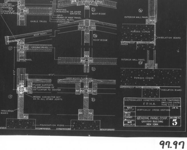
This image presents a framed architectural drawing or blueprint. The drawing contains schematic diagrams that detail various building components for a construction project. It shows cross-sectional views, which depict the layers and materials of walls, floors, and roofing. Visible annotations include descriptions like "HARDWOOD FLOORING," "INSULATION BOARD," "ROOF RIDGE," and "FOUNDATION PIERS." These labels help to identify the specific parts and materials used in construction.
From the image, we can see multiple sections, each providing a different perspective or detail of the building's structure. The design includes elements like trusses, ceiling panels, and wall panels, suggesting attention to both structural integrity and insulation.
In the bottom right, there seems to be a logo or emblem with the text "GENERAL PANEL CORP. GRAYBAR BUILDING NEW YORK." Below that, there is a scale indicator for the drawing, which is common in architectural blueprints to signify the drawing's proportion relative to the actual structure size. The bottom right of the image also has a handwritten mark "99.97," which could be an archival or cataloguing number.
The image is in black and white, and it appears to be a photograph of the actual physical drawing, which is mounted and framed, with a white border around it.
Created by gpt-4o-2024-05-13 on 2024-12-07
The image appears to be a black and white technical drawing or blueprint. It depicts detailed cross-sections and construction diagrams, likely related to building architecture or engineering. Specific elements such as roof trusses, wall panels, ceiling panels, and floor supports are labeled and dimensioned. Various construction materials are indicated, including insulation boards, porous concrete, hardwood flooring, and foundation piers.
Here's a bit more detail on the various sections shown:
- Roof Section: Includes details like "Roof Ridge," "Ceiling Panel," and "Gable Truss."
- Wall Section: Shows "Exterior Wall Panel," "Interior Wall Panel," "Insulation Board," and "Waterproof Paper."
- Floor Section: Depicts "Hardwood Flooring," "Floor Supports," and "Foundation Piers."
There are labels and measurements throughout the drawing to provide specific construction guidelines. Additionally, there is a title block in the lower right corner indicating that this drawing is for sectionalized construction of temporary dwellings by the F.F.H.A., and the type of unit is given as "D.J. Unit." The plans were drawn by General Panel Corp, located in the Graybar Building in New York, with a drawing date of 4/28/45 and drawing no. 5.
The number "99.97" is written on the bottom right of the image, possibly indicating an archive or catalog number.
Anthropic Claude
Created by us.anthropic.claude-3-5-sonnet-20241022-v2:0 on 2025-06-25
This image appears to be an architectural or construction blueprint, specifically showing detailed cross-sectional drawings of building components. It's a technical drawing in white lines on a dark background (likely a negative/blueprint style), showing various construction details including roof panels, ceiling panels, wall panels, flooring, and foundation elements. The drawing includes measurements and annotations for different components like insulation board, waterproof paper, and hardwood flooring. At the bottom of the drawing, there appears to be a title block indicating it's for "FPHA" (Federal Public Housing Authority) dwelling units, and it's labeled as being by "General Panel Corp." The drawing shows vertical cross sections of the construction elements and appears to be numbered "5" in the corner. There's also what appears to be a number "99.97" written outside the main drawing area.
Created by claude-3-haiku-20240307 on 2024-12-07
The image appears to be a detailed technical blueprint or schematic drawing. It shows various cross-sections, dimensions, and labels for different components of a building or structure, such as wall panels, roof beams, insulation, and foundation piers. The drawing seems to be focused on the structural and construction details rather than the overall architectural design. It contains many technical specifications and measurements, indicating it is likely an engineering or architectural drawing used for planning and building purposes.
Created by claude-3-5-sonnet-20241022 on 2024-12-07
This image is an architectural blueprint or technical drawing showing a vertical cross-section of a building structure. It appears to be a negative (white lines on black background) drawing that details various construction elements including:
- Roof ridge and roofing components
- Ceiling panels
- Wall panels (both interior and exterior)
- Hardwood flooring
- Foundation piers
- Insulation board placement
- Porous concrete elements
- Various joints and connectors
The drawing includes detailed annotations and measurements, and appears to be for a FPHA (Federal Public Housing Authority) dwelling unit. In the bottom right corner, there's a title block indicating this is from the General Panel Corporation. The drawing is numbered "5" and has what appears to be a reference number "99.97" written below the frame.
This technical drawing would have been used to guide construction and shows how different building components connect and relate to each other in the overall structure.
Meta Llama
Created by us.meta.llama3-2-11b-instruct-v1:0 on 2024-12-07
The image is a black-and-white architectural drawing of a building's floor plan, presented on a white background with a black border. The drawing is labeled "97.97" in the bottom-right corner.
Key Features:
- Floor Plan: The drawing depicts the interior layout of a building, including various rooms and spaces.
- Labels and Annotations: The drawing includes labels and annotations that identify different features, such as doors, windows, and architectural elements.
- Scale: The drawing is scaled to provide a detailed representation of the building's design.
- Background: The drawing is set against a white background, which helps to highlight the details of the floor plan.
Purpose:
- Architectural Design: The drawing is likely used for architectural design purposes, such as planning and construction.
- Communication: The drawing serves as a visual aid for communication among architects, engineers, and contractors involved in the project.
- Documentation: The drawing provides a permanent record of the building's design, which can be referred to during construction and future renovations.
Conclusion:
The image presents a detailed and informative architectural drawing that showcases the building's floor plan and various features. The drawing is a valuable tool for architects, engineers, and contractors, and it provides a clear understanding of the building's design and layout.
Created by us.meta.llama3-2-90b-instruct-v1:0 on 2024-12-07
The image is a black-and-white architectural drawing of a building's floor plan, with various components labeled. The drawing is set against a white background, surrounded by a black border, and features a handwritten notation "97.97" in the bottom-right corner.
Key Features:
- Floor Plan: The central element of the image, showcasing the layout of the building's floors.
- Labels: Various components are labeled throughout the drawing, including:
- Roofing materials
- Wall panels
- Insulation boards
- Foundation piers
- Other structural elements
- Notation: A handwritten note "97.97" is visible in the bottom-right corner, likely indicating a reference or catalog number.
- Background: The drawing is set against a white background, providing a clean and neutral contrast to the black-and-white architectural design.
- Border: A black border surrounds the drawing, adding a touch of elegance and sophistication to the overall presentation.
Conclusion:
The image presents a detailed and informative architectural drawing of a building's floor plan, complete with labeled components and a notation for reference. The use of a white background and black border adds a touch of professionalism to the design, making it suitable for use in architectural or construction contexts.
Amazon Nova
Created by amazon.nova-lite-v1:0 on 2025-02-25
This image is a technical drawing of a building's cross-section. It shows the various components and materials used in the construction of the building, including the roof, walls, insulation, and foundation. The drawing is labeled with measurements and specifications, indicating the dimensions and materials used for each component. The drawing also includes notes and annotations that provide additional information about the construction process. The image is likely a part of a larger set of technical drawings used for the construction of the building.
Created by amazon.nova-pro-v1:0 on 2025-02-25
The image is a technical drawing of a building's construction details, specifically focusing on the roof and wall sections. The drawing is presented on a black background with white text and lines, which is a common format for architectural blueprints. The drawing includes several sections labeled with specific construction details, such as "roof ridge," "gable truss," "ceiling panel," and "insulation board." There are also measurements and notes about materials like "hardwood flooring" and "waterproof paper." The drawing is dated April 29, 1945, and is signed by "Graybar Building" in New York. The number "97.97" is prominently displayed at the bottom of the drawing, possibly indicating a scale or another specific measurement relevant to the construction.
Google Gemini
Created by gemini-2.0-flash-lite on 2025-04-28
The image is a detailed architectural drawing, presented in black and white. It's a sectional view of a building, likely a temporary dwelling unit, as indicated by the text "SECTIONALIZED CONSTRUCTION FOR TEMPORARY DWELLING UNITS TYPE T.D-U-1."
The drawing clearly illustrates various structural elements, including:
- Roofing: Details showing the roofing materials, including "ROOFING - HOMASOTE OR OTHER MATERIAL," and a gable truss.
- Walls: The exterior and interior wall panels are defined, with the use of porous concrete and insulation board.
- Flooring: "HARDWOOD FLOORING" is labeled.
- Structural Components: The drawing specifies the use of 2x3 and 2x4 timber members, with annotations for "FLOOR SUPPORTS IN DISTANCES OF 22 CENTER TO CENTER."
- Foundation: "FOUNDATION PIERS" are indicated at the base.
- Connections: Details include a "WEDGE CONNECTOR SET AS IN ALL OTHER JOINTS."
The drawing is labeled with the General Panel Corp., located in the Graybar Building in New York. The drawing number is 5. The scale is 1/4 = 1." The diagram provides a technical, instructive look into the building's design and construction.
Created by gemini-2.0-flash on 2025-04-28
Here is a description of the image:
The image is a black and white technical drawing of a sectionalized construction for temporary dwelling units. It is labeled as "SECTIONALIZED CONSTRUCTION FOR TEMPORARY DWELLING UNITS TYPE T.D-U-1," and is a vertically cross section. The drawing includes details of the Gable Truss, Roof Ridge, Exterior Wall Panel, Interior Wall Panel, and Foundation Piers. Various materials are noted in the diagram, such as Homosote, Porous Concr., Waterproof Paper, and Insulation Board. There are also notes on measurements, such as "Floor supports in distances of 22" center to center" and "Hardwood Flooring."
The drawing is labeled "General Panel Corp. Graybar Building, New York", with "Drawing No. 5" visible in the lower right corner. Scale: 1/4" : 1', the image shows it was drawn on April 28, 1943.
Below the drawing is the handwritten number sequence "92.92".
Mistral Pixtral
Created by us.mistral.pixtral-large-2502-v1:0 on 2025-04-28
The image is a detailed architectural drawing that appears to be a sectional view of a building's structural components. The drawing is labeled "General Panel Corp., Graybar Building, N.Y., N.Y. 1966" and it is dated "5/25/66." The drawing is divided into several sections, each labeled with a number and description, which outline various structural elements of the building.
Here is a breakdown of the key components shown in the drawing:
Section 1 (Top Left):
- Shows a gable truss with roof panels and insulation.
- Includes a ventilation opening and a distance of 10 feet and 6 inches.
Section 2 (Top Center):
- Depicts a roof ridge with mounting brackets or other materials.
- Shows a grid of roof panels and ceiling panel hooks/ties.
Section 3 (Top Right):
- Illustrates an exterior wall panel with porous concrete and insulation board.
- Includes waterproof paper and an interior wall panel.
Section 4 (Middle Left):
- Displays a wall panel with a roof panel and ceiling panel.
- Shows a 2x4 wood frame and insulation board.
Section 5 (Middle Center):
- Depicts a roof ridge with roof panels and a 2x4 wood frame.
- Includes insulation and a ceiling panel.
Section 6 (Middle Right):
- Shows a floor panel with hardwood flooring.
- Includes a 2x4 wood frame and insulation board.
Section 7 (Bottom Left):
- Illustrates a foundation pier with a wedge connector set.
- Shows insulation board and a distance of 10 feet.
Section 8 (Bottom Center):
- Depicts a foundation pier with a 2x4 wood frame.
- Includes insulation board and a distance of 2 feet and 6 inches.
Section 9 (Bottom Right):
- Shows sectionalized construction for temporary protection against fire (F.P.H.A. Type 3, Class 1).
- Includes vertically cross-sectioned details and insulation board.
The drawing provides a comprehensive view of the structural elements, including the roof, walls, floor, and foundation, with detailed measurements and material specifications. This type of drawing is typically used in construction and engineering to ensure accurate assembly and compliance with building codes.
Qwen
Created by Qwen/Qwen2.5-VL-7B-Instruct on 2025-07-26
The image appears to be an architectural or engineering blueprint or plan, specifically a cross-sectional drawing for a dwelling unit. The drawing is labeled "Sectionalized Construction for Temporary Dwelling Units Type T.O.U.-I." It includes detailed annotations and dimensions for various components of the construction, such as the roof, walls, floor, and foundation. Notable elements include:
- Roof paneling with details for a gable truss and grid frame.
- Exterior and interior wall panels.
- Insulation boards.
- Porous concrete layers.
- Waterproofing materials.
- Foundation piers.
The drawing is attributed to General Panel Corp. for the Graybar Building in New York, and it is dated April 26, 1943. The scale is noted as 1/4" = 1'. There are also specific dimensions and labels such as "2X6" and "2X4" for wooden components, and "22" center to center" for floor supports.
Created by Qwen/Qwen2.5-VL-72B-Instruct on 2025-07-26
This image is a blueprint or architectural drawing, presented in black and white. It depicts detailed cross-sectional views of a building's construction, showcasing various sections of the structure including the roof, walls, and foundation.
Key features of the image include:
Roof and Trusses: The top part of the drawing shows the roof structure with trusses, detailing the materials and assembly of the roofing system. Terms like "gable truss," "roof panel," and "roof ridge" are visible.
Wall Panels: The drawing includes cross-sections of the exterior and interior wall panels. Materials such as "porous concrete," "waterproof paper," and "insulation board" are labeled.
Flooring and Foundation: The bottom part of the drawing shows the flooring system, including "hardwood flooring," and the foundation piers. Dimensions and specifications for the floor supports and foundation are provided.
Annotations and Labels: Throughout the drawing, there are numerous annotations and labels that specify materials, dimensions, and construction details. The text is small but provides critical information for building the structure.
Title Block: The bottom right corner of the drawing contains a title block with additional information such as the drawing number (5), the date (April 20, 1945), and the location (New York). The title block also mentions "General Panel Corp" and "Graybar Building," indicating the company and location associated with the drawing.
Scaling Information: The drawing includes a scale indicating the ratio used for the cross-sectional views, which is "1/4" = 1'".
The overall purpose of this blueprint is to provide detailed instructions and specifications for the construction of a temporary dwelling unit, as indicated by the text "Sectionalized Construction for Temporary E.P.H.A. Dwelling Units" at the bottom of the drawing.
Text analysis
Amazon