
Machine Generated Data
Tags
Color Analysis
Feature analysis
Amazon
Clarifai
AWS Rekognition
| Monitor | 85.1% | |

Categories
Imagga
created on 2022-06-04
| text visuals | 81.7% | |
| interior objects | 9.4% | |
| streetview architecture | 7.7% | |
Captions
Microsoft
created by unknown on 2022-06-04
| a flat screen tv sitting on top of a blackboard | 76.6% | |
| a flat screen tv sitting on top of a table | 48.6% | |
| a flat screen tv sitting on top of a desk | 48.5% | |
Clarifai
No captions written
Salesforce
Created by general-english-image-caption-blip on 2025-05-21
a photograph of a black and white photo of a house plan
Created by general-english-image-caption-blip-2 on 2025-07-02
a black and white photograph of a blueprint of a house
OpenAI GPT
Created by gpt-4 on 2024-12-07
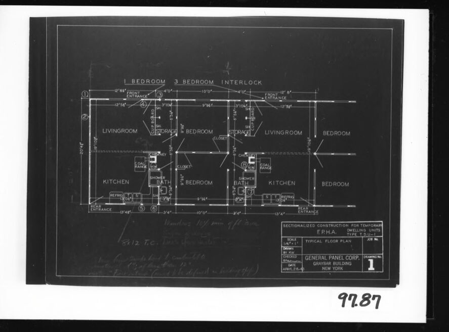
This image is a black and white photo of a floor plan blueprint. The layout appears to detail a duplex with mirrored living spaces. Each unit includes a living room, kitchen, bathroom, and bedrooms. The plan shows the dimensions of rooms and the placement of doors, windows, and fixtures like the kitchen sink, bath, and shower. Annotations and labels are present, giving more information about the spaces and construction notes.
There are textual notes on the blueprint, including references to "SECTIONALIZED CONSTRUCTION FOR TEMPORARY F.E.H.A. DWELLING UNITS" and "GENERAL PANEL CORP. GRAYBAR BUILDING, NEW YORK". This suggests that the blueprint may have been for temporary housing units designed by the Federal Emergency Housing Administration or a similar entity. The date on the blueprint is marked April 29, 1940.
Created by gpt-4o-2024-05-13 on 2024-12-07
The image depicted is a drafted floor plan for a dwelling unit. The plan outlines the layout of the house with labeled rooms and dimensions.
The labeled rooms in the plan include:
- Living Room
- Kitchen
- Bedroom
- Bath
- Storage
The plan appears to include detailed measurements in feet and inches, entrances, and the placement of various fixtures. At the bottom right corner, there is an information box that reads:
- “SECTIONALIZED CONSTRUCTION FOR TEMPORARY DWELLING UNITS
- F.P.H.A. TYPE T.D.L.L 1
- TYPICAL FLOOR PLAN
- SCALE 1/4"=1'-0
- DRAWING NO. 1
- GENERAL PANEL CORP. GRAYBAR BUILDING NEW YORK
- DATE APRIL 15, 1942
There are other notations, which appear to include some handwriting and additional construction-related details. The number "9287" and "97.87" is written outside the plan on the white border of the paper, which might refer to a cataloging or reference system.
Anthropic Claude
Created by claude-3-haiku-20240307 on 2024-12-07
The image appears to be a technical blueprint or floor plan for a residential dwelling. It shows the layout and dimensions of a multi-bedroom unit, including a living room, kitchen, and bathrooms. The plan is labeled "TYPICAL FLOOR PLAN" and appears to be from the "GENERAL PANEL CORP." construction company based in New York. The image is a black and white technical drawing without any human figures.
Created by claude-3-5-sonnet-20241022 on 2024-12-07
This is an architectural blueprint or floor plan showing the layout for temporary dwelling units. The drawing appears to be a negative (white lines on dark background) and shows two connected living spaces - a 1-bedroom unit and a 3-bedroom unit with an interlock between them.
The floor plan includes detailed measurements and shows the layout of:
- Living rooms
- Bedrooms
- Kitchens
- Bathrooms with shower facilities
- Various entrances
The drawing was created by General Panel Corp., Glenview Building, as indicated in the title block in the lower right corner. It's labeled as "Sectionalized Construction for Temporary FPHA Dwelling Units" and appears to be drawing number 1.
The plan shows an efficient use of space with shared walls between units and appears to be designed for multi-family housing. The number "9989" is visible in the bottom right corner of the photograph.
Created by us.anthropic.claude-3-5-sonnet-20241022-v2:0 on 2025-06-26
This image shows an architectural blueprint or floor plan for what appears to be a duplex or multi-unit residential building. The plan is drawn in white lines on a dark background and shows two mirrored living units. Each unit contains:
- A living room
- A kitchen
- 3 bedrooms
- A bathroom
- Various entrances and corridors
The units are connected by what's labeled as an "interlock" area at the top of the drawing. Dimensions are marked throughout the plan, and it appears to be a technical drawing created by General Panel Corp. for the "Glenview Building." The drawing is labeled as "Sectionalized Construction for Temporary Dwelling Units" and appears to be part of an FPHA (Federal Public Housing Authority) project. The drawing has a scale and other technical specifications noted in the bottom right corner.
Meta Llama
Created by us.meta.llama3-2-11b-instruct-v1:0 on 2024-12-07
The image presents a black and white floor plan for a residential building, specifically designed to accommodate three bedrooms, two bathrooms, a kitchen, living room, and storage areas. The floor plan is meticulously labeled with dimensions and room names, providing a clear understanding of the layout.
Key Features:
- Bedrooms: Three bedrooms are located on the upper floor, each with its own closet space.
- Bathrooms: Two bathrooms are situated on the upper floor, one adjacent to the bedrooms and another near the living room.
- Kitchen: A kitchen is positioned on the lower floor, featuring a refrigerator and stove.
- Living Room: A living room is located on the lower floor, adjacent to the kitchen.
- Storage Areas: Storage areas are designated on both floors, providing ample space for household items.
- Dimensions: The floor plan includes detailed dimensions for each room, ensuring accurate measurements and layout.
- Labels: Room names and labels are clearly indicated throughout the floor plan, facilitating easy identification of each area.
- Scale: A scale is provided in the bottom-right corner, allowing users to accurately measure the floor plan.
- Date: The date "12-1-1949" is handwritten in the bottom-left corner, indicating when the floor plan was created.
- Company: The company name "GENERAL PANEL CORP." is listed in the bottom-right corner, along with the address "GRAYSMITH BUILDING NEW YORK."
Conclusion:
The floor plan provides a comprehensive overview of the residential building's layout, including the location of bedrooms, bathrooms, kitchen, living room, and storage areas. The inclusion of dimensions, labels, and a scale ensures accuracy and clarity, making it an essential tool for architects, builders, and homeowners alike.
Created by us.meta.llama3-2-90b-instruct-v1:0 on 2024-12-07
This image is a black-and-white blueprint of a floor plan for a three-bedroom apartment. The blueprint is presented on a white background, with a black border around it. The floor plan is drawn in white lines and text on a black background, providing a clear visual representation of the apartment's layout.
The floor plan shows the location of each room, including the bedrooms, living room, kitchen, and bathrooms. It also indicates the placement of doors, windows, and other architectural features. The blueprint appears to be a technical drawing, likely created by an architect or engineer, and is intended to provide a detailed and accurate representation of the apartment's design.
Overall, this image provides a clear and concise visual representation of the floor plan for a three-bedroom apartment, making it useful for architects, engineers, builders, and anyone interested in understanding the layout and design of the space.
Amazon Nova
Created by amazon.nova-lite-v1:0 on 2025-02-24
The image is a floor plan of a building, possibly a residential building, with a total of five bedrooms and two bathrooms. The floor plan is divided into two sections, with the left section labeled "INTERLOCK" and the right section labeled "BEDROOM." The floor plan includes the dimensions of each room, as well as the location of the entrance, living room, kitchen, and bathroom. The drawing also includes a label for the "SECTIONALIZED CONSTRUCTION FOR TEMPORARY DWELLING UNITS" and a job number. The image is a black-and-white drawing on a white background.
Created by amazon.nova-pro-v1:0 on 2025-02-24
The image is a floor plan of a three-bedroom house, presented in a black and white format. The layout is organized with rooms labeled and dimensions provided for each space. The house features three bedrooms, a living room, and a kitchen. Each bedroom is equipped with a closet, and two of them have an attached bathroom. The living room is centrally located, and the kitchen is positioned adjacent to it. The floor plan also includes a section for temporary construction details, such as the scale, date, and the name of the architect or designer.
Google Gemini
Created by gemini-2.0-flash-lite on 2025-04-28
The image presents a blueprint, likely a floor plan for a housing project. The blueprint is labeled "SECTIONALIZED CONSTRUCTION FOR TEMPORARY DWELLING UNITS TYPE TDU" and details two units, a 1 bedroom and a 3 bedroom. The units are in an "interlock" arrangement. The plan highlights the layout of rooms, including living rooms, bedrooms, kitchens, and bathrooms. The blueprint also indicates the dimensions of rooms and architectural elements. Additional notes and inscriptions are present, including those about building specifications and identification markings. The overall context suggests a construction or architectural design document.
Created by gemini-2.0-flash on 2025-04-28
Here is a description of the image:
The image is a black and white photograph of a blueprint or architectural plan, placed within a black and white double border, with a visible number "97.87" written on the outer border. The document appears to be an architectural layout, possibly for prefabricated or temporary housing units. It illustrates a floor plan of a section, labeled as "1 Bedroom" and "3 Bedroom Interlock".
The plan is highly detailed, including labels for various rooms such as living rooms, bedrooms, kitchens, and bathrooms. Key features like storage spaces, closets, refrigerators, and coal ranges are marked within the layout. Specific dimensions for rooms and passages are provided in feet and inches. The bottom of the document includes labels for: SECTIONALIZED CONSTRUCTION FOR TEMPORARY DWELLING UNITS.
The architectural plan is titled "TYPICAL FLOOR PLAN", and the name of the company "GENERAL PANEL CORP." along with their location "GRAYBAR BUILDING NEW YORK" are printed at the bottom. There is a label "DRAWING NO. 1".
Mistral Pixtral
Created by us.mistral.pixtral-large-2502-v1:0 on 2025-04-28
The image is a black-and-white architectural floor plan for a housing unit. The plan appears to be for a multi-unit building, specifically showing two adjacent units. Each unit is labeled as having one bedroom and three bedrooms, respectively, with an interlocking design.
Key Features of the Floor Plan:
Units Layout:
Left Unit:
- Living Room: Located at the front, adjacent to the entrance.
- Kitchen: Positioned next to the living room.
- Bedroom: Situated next to the kitchen.
- Bathroom: Accessible from the bedroom.
- Storage: Located near the entrance and bedroom.
- Entrance: At the front of the unit.
Right Unit:
- Living Room: Located at the front, adjacent to the entrance.
- Kitchen: Positioned next to the living room.
- Three Bedrooms: Arranged in a row, with closets in each bedroom.
- Bathroom: Accessible from the hallway connecting the bedrooms.
- Storage: Located near the entrance and bedrooms.
- Entrance: At the front of the unit.
Dimensions:
- The floor plan includes various measurements for the rooms and spaces, indicating the size and layout of each area.
Labels and Annotations:
- The plan includes labels for different rooms and spaces, such as "LIVING ROOM," "KITCHEN," "BEDROOM," "BATH," and "STORAGE."
- There are also annotations indicating specific features like closets, entrances, and interlocking sections.
Additional Information:
- The floor plan is titled "Sectionalized Construction for Temporary F.P.H.A. Multiple Dwellings."
- It is marked as "Drawing No. 1" and includes details about the scale and the drawing number.
- The plan is attributed to the General Panel Corp., located in the Graybar Building, New York.
Handwritten Notes:
- There are handwritten notes at the bottom of the plan, which appear to be instructions or comments related to the construction or use of the plan.
This floor plan provides a detailed layout for temporary housing units, showing the arrangement of rooms, dimensions, and specific features for each unit.
Qwen
Created by Qwen/Qwen2.5-VL-7B-Instruct on 2025-07-26
The image is a floor plan for a three-bedroom dwelling unit with an interlock. The layout includes the following main features labeled in the drawing:
- Bedrooms: There are three bedrooms, each with dimensions provided.
- Living Rooms: Two living rooms are shown, one on the left and one on the right.
- Kitchen: The kitchen is located towards the lower left side of the plan.
- Bathrooms: There are two bathrooms, one near the kitchen and the other near the center of the plan.
- Storage: There is a designated storage area near the center of the plan.
- Closets: Several closets are indicated, with dimensions for one labeled.
- Entrances: There are two entrances, one labeled as "FRONT ENTRANCE" and the other labeled as "REAR ENTRANCE."
The plan is sectioned into different areas with dimensions provided for each section. The bottom right corner of the image includes a label with "97.87" and is framed with a black border. There is also a legend at the bottom right corner that refers to the "Sectionalized Construction for Temporary Dwelling Units Type TDU-1" by General Panel Corp., dated April 28, 1948.
Created by Qwen/Qwen2.5-VL-72B-Instruct on 2025-07-26
This image is an architectural blueprint of a three-bedroom house plan. Here's a detailed description:
Title and Information:
- The title at the bottom right indicates that this is a "Typical Floor Plan" for a "Sectionalized Construction for Temporary Dwelling Units Type T.D.U.-1."
- It is created by the "General Panel Corp., Graybar Building, New York."
- The drawing number is "1," and the date is "April 26, 1944."
- The scale is labeled as 1/4" = 1'.
Layout:
- The plan is divided into two symmetrical sections labeled as "BEDROOM 3" and "INTERLOCK."
- Each section has a "LIVINGROOM," "BEDROOM," "KITCHEN," and a "BATH."
- The "KITCHEN" area in each section includes a "REFRO" (refrigerator), "SINK," and a "COAL HATCH."
- The "BATH" area includes a "SHOWER," "SINK," and a "TOILET."
- Each bedroom has a "CLOSET."
- There are "STORAGE" areas labeled in each section.
Dimensions:
- Dimensions are provided for various parts of the house, such as the width of the "FRONT ENTRANCE" and "REAR ENTRANCE," and the size of the "LIVINGROOM," "BEDROOM," "KITCHEN," and "BATH."
Additional Notes:
- There are handwritten notes at the bottom left, possibly indicating additional specifications or notes for the construction team.
The blueprint is well-organized, providing clear details for the construction of a temporary dwelling unit.
Text analysis
Amazon


