Machine Generated Data
Tags
Color Analysis
Feature analysis
Amazon
Clarifai
AWS Rekognition
| Monitor | 98.6% | |


Categories
Imagga
created on 2022-06-04
| streetview architecture | 49.6% | |
| text visuals | 42.7% | |
| interior objects | 5.1% | |
| paintings art | 2% | |
Captions
Microsoft
created by unknown on 2022-06-04
| a flat screen television | 67.2% | |
| a flat screen tv sitting on top of a television | 47.4% | |
| a flat screen tv | 47.3% | |
Clarifai
No captions written
Salesforce
Created by general-english-image-caption-blip on 2025-05-21
a photograph of a black and white photo of a building with a black and white drawing of a
Created by general-english-image-caption-blip-2 on 2025-06-28
a black and white photograph of a house with two windows
OpenAI GPT
Created by gpt-4 on 2024-12-07
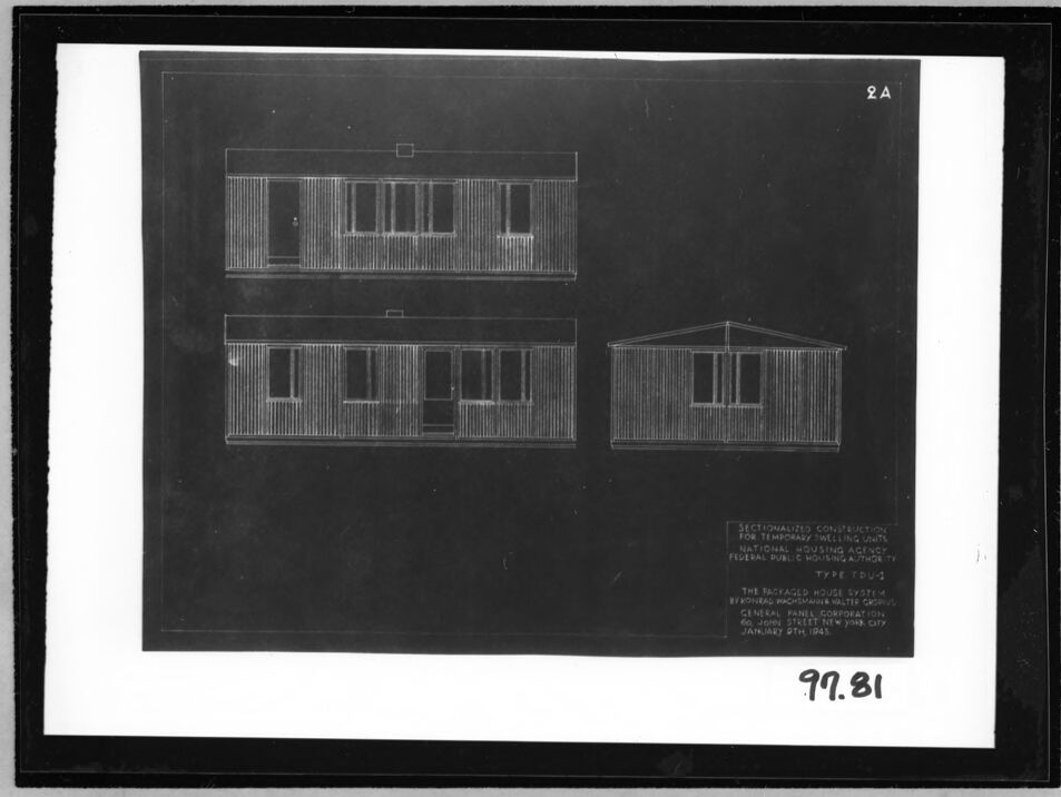
The image displays an architectural blueprint or drawing of a structure, presented in white lines on a dark background. There are three separate elevations or views of the building portrayed:
The top-left view appears to be the front elevation of a two-story building with multiple windows and what might be a balcony or an extended structure on the upper floor.
Directly below the top-left view is another elevation, presumably the rear side of the same building, showing a similar pattern of windows and structural design.
The top-right view is a different perspective, likely a side elevation, showing a gable roof with windows on the end wall.
There is text at the bottom right of the image, which appears to be a description or title related to the architectural work. However, the text is not legible due to the resolution in the provided image. Since it's a scanned copy of the original blueprint or drawing, we can see the dark border of the scanning bed, and the image has a catalog number or reference code (99.81) at the bottom right corner outside the main frame of the drawing. Additionally, there's a label "2A" in the top-right corner, possibly indicating a series or set to which this drawing belongs.
Architectural drawings like this are typically used for the planning and construction of buildings, providing detailed visual representation for architects, engineers, and builders to follow.
Created by gpt-4o-2024-05-13 on 2024-12-07
This image shows a black and white photograph of a blueprint or architectural drawing. It depicts three different views of a rectangular building structure, most likely a sectionalized temporary dwelling unit. The views include:
- A front elevation view showing the structure's front facade with vertical lines perhaps indicating siding or paneling.
- A rear elevation view which also displays siding or paneling details.
- A side elevation view presenting a single facade with the same vertical lines, consistent with the other views.
There is a section of text on the bottom right corner of the blueprint that reads:
"SECTIONALIZED CONSTRUCTION FOR TEMPORARY DWELLING UNITS NATIONAL HOUSING AGENCY FEDERAL PUBLIC HOUSING AUTHORITY TYPE D4-T THE TRAEGERD HOUSE SYSTEM STYRON, PENDLEBURY & WALTER CORP. GENERAL PANEL CORPORATION 63 JOHN STREET NEW YORK CITY, JANUARY 4TH 1943"
A handwritten number “99.81” is present in the bottom right corner of the photograph.
Anthropic Claude
Created by us.anthropic.claude-3-5-sonnet-20241022-v2:0 on 2025-06-24
This image appears to be an architectural drawing or blueprint showing different elevations of a temporary dwelling unit. The drawing is done in white lines on a dark background, showing three views of what appears to be a modest residential structure. The views include what look like front, side, and possibly rear elevations of a simple rectangular building with vertical siding or panels and windows. The drawing appears to be labeled as a "Type TDU-3" and includes some text at the bottom that suggests it may be related to national housing or a general panel corporation, dated around January 1943. This seems to be documentation for standardized temporary housing units, possibly from the World War II era.
Created by claude-3-haiku-20240307 on 2024-12-07
The image appears to be a blueprint or architectural drawing of multiple modular or prefabricated structures, likely intended for temporary or emergency housing. The drawing shows three separate views or designs, with different configurations of window placements and roof styles. There are technical details and specifications provided at the bottom of the image, suggesting this is a technical document or plan for the construction of these structures.
Created by claude-3-5-sonnet-20241022 on 2024-12-07
This appears to be an architectural drawing or blueprint showing different elevations of a temporary dwelling unit. The image shows three different views of what seems to be a simple, modular housing structure. The top view shows a side elevation with vertical siding and windows, the middle shows what appears to be the front elevation with a door and windows, and the right side shows another perspective of the structure. The drawings are done in white lines on a dark background, giving it the appearance of a negative or blueprint style drawing. At the bottom of the image, there appears to be some text or specifications, though it's not clearly legible in this reproduction. The image has the number "99.81" written or printed in the bottom right corner.
Meta Llama
Created by us.meta.llama3-2-11b-instruct-v1:0 on 2024-12-07
The image presents a black-and-white blueprint for a temporary housing unit, showcasing the design and layout of the structure.
Key Features:
- Title: The title "SECTIONALIZED CONSTRUCTION FOR TEMPORARY DWELLING UNITS" is prominently displayed at the bottom right corner of the blueprint.
- Design: The blueprint features a rectangular shape with a flat roof and a single-story design. It has a total of six windows, evenly distributed across the front and back sides of the structure.
- Dimensions: The blueprint provides detailed measurements for the structure, including its length, width, and height. The length is 30 feet, the width is 12 feet, and the height is 9 feet.
- Materials: The blueprint specifies that the structure is made of wood, with a corrugated metal exterior and a wooden interior.
- Purpose: The blueprint was created by the National Housing Agency for the purpose of providing temporary housing units during World War II.
- Date: The blueprint was created on January 9th, 1943, and is marked with the number "97.81" in the bottom-right corner.
Summary:
The blueprint provides a detailed design and layout for a temporary housing unit, including its dimensions, materials, and purpose. The structure is designed to be functional and efficient, with a simple yet effective design that meets the needs of those who will be using it.
Created by us.meta.llama3-2-90b-instruct-v1:0 on 2024-12-07
The image depicts a black and white architectural drawing of a house, showcasing its front and side elevations. The drawing is presented on a white background with a black border, featuring a prominent black rectangle that contains the architectural design.
Key Features:
- Front Elevation: The front elevation of the house is displayed at the top left of the drawing, while the side elevation is shown at the bottom left.
- Side Elevation: The side elevation is depicted at the right side of the drawing.
- Labeling: The drawing includes labels and text, although they are not legible due to the low resolution of the image.
- Date: The date "97.81" is handwritten in black ink at the bottom right corner of the image, suggesting that it may be a reference number or a date related to the drawing.
Overall Impression:
The image appears to be a historical or archival document, possibly from the early 20th century, given the style of the architectural drawing and the use of black and white media. The presence of a date and labels suggests that the drawing was created for a specific purpose, such as a building project or a design competition. However, without further information, it is difficult to determine the exact context or significance of the image.
Amazon Nova
Created by amazon.nova-lite-v1:0 on 2025-02-27
The image is a black-and-white architectural drawing. It shows three different floor plans of a building. The drawing is labeled with the number "2A" at the top right corner. Below the floor plans, there is a label that reads "SECTIONALIZED CONSTRUCTION FOR TEMPORARY HOUSING UNITS" and "NATIONAL HOUSING AGENCY FEDERAL PUBLIC HOUSING AUTHORITY." Below that, there is a label that reads "TYPE EDUS" and "BY THE PACKAGED HOUSE SYSTEM BY FEDERAL WACHSMINSTER WOLTERS GROUP." Below that, there is a label that reads "GENERAL PANEL CORPORATION 450 JOHN STREET NEW YORK CITY JANUARY 9TH 1943." At the bottom of the drawing, there is a number "97.81."
Created by amazon.nova-pro-v1:0 on 2025-02-27
The image is a black and white architectural blueprint of a building. The blueprint is divided into three sections. The top section shows the front elevation of the building, while the middle section shows the side elevation. The bottom section shows the floor plan of the building. The blueprint also includes text that reads "Sectionalized Construction for Temporary Dwelling Units" and "National Housing Agency Federal Public Housing Authority Type FDUS." The blueprint is dated January 9th, 1943.
Google Gemini
Created by gemini-2.0-flash-lite on 2025-04-28
Here's a description of the image:
Overall Impression:
The image is a black and white architectural drawing or blueprint. It's a design for temporary dwelling units, likely for housing. The drawing is labeled and appears to be a plan for construction.
Key Features:
- Multiple Views: The drawing presents different views of the dwelling unit, likely including elevations or side views.
- Architectural Style: The structures seem to have a simple, utilitarian design. They feature a rectangular shape with windows and doors.
- Labeling: The image includes text indicating it's "Sectionalized Construction" for temporary dwellings. Details about the "National Housing Agency" and "Federal Public Housing Authority" are mentioned. There is also reference to "Type TDU-1" and names of architects and the "General Panel Corporation" is the project.
- Date: The drawing is dated "January 9th 1943".
- Number: The lower right of the blueprint has the number "97.81" written beneath the image.
Possible Context:
Based on the labeling, the image appears to be related to housing programs during a specific historical period. Given the date (1943), it's likely related to efforts to provide temporary housing.
Created by gemini-2.0-flash on 2025-04-28
Here's a description of the image:
The image appears to be a black and white photograph of a blueprint or technical drawing. The drawing is of "Sectionalized Construction for Temporary Dwelling Units" by the National Housing Agency Federal Public Housing Authority (Type TOU-1). It is "The Packaged House System by Konrad Wachsmann & Walter Gropius" from the General Panel Corporation, 60 John Street, New York City, January 9th 1943.
The blueprint shows multiple elevations of a small, rectangular structure. It includes two side views and one end view, showing doors and windows. At the top right of the blueprint is the number "2A". At the bottom of the blueprint is the number "97.81".
The blueprint is mounted on a white backing and is framed by a dark border.
Mistral Pixtral
Created by us.mistral.pixtral-large-2502-v1:0 on 2025-04-28
The image is a black-and-white photograph of a blueprint or architectural drawing. It features three different views of a sectionalized construction for temporary dwelling units, as authorized by the Federal Public Housing Authority. The design is labeled as "Type FDU-3."
Top View: This appears to be a side elevation of a two-story structure. It has a simple rectangular shape with a flat roof. The upper floor has several windows, suggesting multiple rooms or living spaces.
Middle View: This is a front elevation of a single-story structure with a porch area. The structure has a gabled roof, and the front facade features multiple windows and a door, indicating the main entrance.
Right View: This is another side elevation of a single-story structure, similar to the middle view but without the porch. It also has a gabled roof and several windows along the side.
The blueprint includes text at the bottom right corner that reads:
"Sectionalized Construction for Temporary Dwelling Units Approved by the Federal Public Housing Authority Type FDU-3 The Packaged House System By General Panel Corporation 120 Broadway, New York City January 9th, 1941"
Additionally, there is a number "99.81" written at the bottom center of the image, which might be a reference or catalog number. The blueprint is framed with a thick black border.
Qwen
Created by Qwen/Qwen2.5-VL-7B-Instruct on 2025-07-26
The image appears to be a technical drawing or blueprint, likely a architectural or engineering design. It features a black and white illustration of a prefabricated house design, specifically labeled as "Type TDU-1." The drawing includes three views of the house: the front elevation, the side elevation, and a top-down perspective.
The text on the right side of the drawing indicates that it is related to "Regionalized Construction for Temporary Housing Units" by the National Housing Agency and the Federal Public Housing Authority. It mentions "The Packaged House System" and provides an address and a date associated with the design: "General Chemical Corporation, 60 John Street, New York City, January 9th, 1943."
The drawing is framed by a black border and is marked with the number "2A" at the top right corner. There is also a handwritten number "97.81" at the bottom right corner, which might be an inventory or catalog number. The style of the illustration and the accompanying text suggests that this is a historical document, likely related to wartime housing solutions or temporary housing units.
Created by Qwen/Qwen2.5-VL-72B-Instruct on 2025-07-26
This image is a black and white architectural blueprint or technical drawing. It appears to depict house plans, specifically for temporary housing units. The drawing includes three separate sections of a house, likely showing different angles or components of the structure. The text in the bottom right corner provides information about the design, indicating it is for the "Packaged House System" by Bachman Walter Corp. and General Electric Corporation, and it is dated January 5th, 1945. The drawing is labeled "2A" and "97.81". The overall style and details suggest it is a historical document related to housing design during the mid-20th century.
Text analysis
Amazon