Machine Generated Data
Tags
Color Analysis
Feature analysis
Amazon

| Monitor | 89.5% | |
Categories
Imagga
| streetview architecture | 99.4% | |
Captions
Microsoft
created on 2022-06-04
| a screen shot of a computer | 58.3% | |
| a close up of text on a screen | 58.2% | |
| a close up of a screen | 58.1% | |
OpenAI GPT
Created by gpt-4 on 2024-12-07
This image displays a blueprint or architectural drawing of a building. The drawing is depicted in white lines on a dark background, which is characteristic of a blueprint's negative image. The blueprint shows an elevation and a section view of a structure with multiple windows and what appears to be a porch or balcony feature. There is text that indicates the scale of the elevation as "1/8 inch to 1 foot." In the lower right-hand corner, additional information is provided about the construction, mentioning "Sectionalized construction for temporary dwellings, National Housing Agency, Federal Public Housing Authority." It also includes the name of the architects or firm responsible for the design, "The Radburn Associates, Architects by Richard M. Bennett, Partner in Charge, General Panel Corporation, January 8, 1945". There's a reference number "9120" provided as well, possibly relating to project or blueprint cataloging. The presentation of the image indicates it might be a photograph of the actual blueprint, as seen by the matte border surrounding the drawing.
Created by gpt-4o-2024-05-13 on 2024-12-07
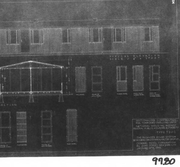
The image appears to be a blueprint or technical drawing. It depicts architectural plans and elevations of a building. The blueprint shows the front elevation labeled "Typical Elevation" and includes various structural and window details. There are sections detailing the wall frame, floor frame, window panel, panel joint, and base for column support. The lower right corner contains a title block that reads: "SECTIONALIZED CONSTRUCTION FOR TEMPORARY DWELLING UNITS NATIONAL HOUSING AGENCY FEDERAL PUBLIC HOUSING AUTHORITY TYPE TDU-1 THE PACKAGED HOUSE SYSTEM BY RICHARD BUCKMINSTER FULLER (FORUM) PUZZLE FARMS CORPORATION GENERAL PANEL CORPORATION NEW YORK CITY, NEW YORK JANUARY 30TH, 1941" In the bottom right corner of the image, the number "99.20" is written.
Anthropic Claude
Created by claude-3-haiku-20240307 on 2024-12-07
The image appears to be an architectural blueprint or technical drawing of a building structure. The drawing shows the elevation, or side view, of a modular building or temporary dwelling. It includes details like the window and door placements, as well as construction specifications and notes. The image does not contain any human faces or identifiable individuals.
Created by claude-3-5-sonnet-20241022 on 2024-12-07
This appears to be an architectural blueprint or technical drawing showing various views of what seems to be a prefabricated or modular house design. The drawing includes: 1. A typical elevation view showing a single-story structure with six windows and two doors across the front 2. A cross-section view showing the roof truss system and foundation details 3. Several smaller detail drawings showing window and door specifications 4. The drawings appear to be from the Federal Public Housing Authority, labeled as "Type V2V-1" The drawing style is typical of mid-20th century architectural documentation, with white lines on a dark background. The structure appears to be a basic rectangular design with vertical siding and a simple pitched roof. This type of drawing would have been used for construction or documentation purposes, likely for public housing projects.
Meta Llama
Created by us.meta.llama3-2-11b-instruct-v1:0 on 2024-12-07
The image is a black and white architectural drawing of a building, with a detailed section of the front elevation and various windows and doors. The drawing is labeled "Type TDU-2" and includes a list of materials and dimensions. * **Building Design** + The building has a rectangular shape with a flat roof. + It has two stories, with a total of 10 windows and 4 doors. + The windows are evenly spaced along the front elevation, with two larger windows on either side of the central door. + The doors are located at the center of each floor, with a small window above each door. * **Sectional View** + The sectional view shows the interior of the building, including the walls, floors, and ceilings. + The walls are made of wood, with a layer of insulation between them. + The floors are made of concrete, with a layer of carpeting on top. + The ceilings are made of drywall, with a layer of acoustic tile above. * **Materials and Dimensions** + The drawing includes a list of materials used in the construction of the building, including wood, steel, and concrete. + The dimensions of the building are also included, with measurements in feet and inches. * **Labels and Annotations** + The drawing includes several labels and annotations, including the title "Type TDU-2" and the date "January 9th, 1938". + There are also several handwritten notes and corrections throughout the drawing. Overall, the image provides a detailed and accurate representation of the building's design and construction. The sectional view and material list provide valuable information for architects, engineers, and builders.
Created by us.meta.llama3-2-90b-instruct-v1:0 on 2024-12-07
The image depicts a black-and-white architectural drawing of a building, likely a house. The drawing is presented in a landscape orientation and features a white border around the edges. The top section of the drawing showcases the front elevation of the building, while the bottom section displays the floor plan. In the top-right corner of the drawing, the number "2" is visible, indicating that this may be part of a larger set of drawings. Below the front elevation, a series of small rectangles are arranged horizontally, each representing a window or door on the building's facade. These rectangles are labeled with numbers, suggesting that they correspond to specific features or components of the building. On the left side of the drawing, a cross-section of the building is depicted, providing a detailed view of its internal structure. This section is also labeled with numbers, which likely refer to specific dimensions or measurements. At the bottom of the drawing, a key or legend is provided, explaining the symbols and abbreviations used throughout the drawing. This key helps to clarify the meaning of various elements, such as walls, doors, and windows. Overall, the image presents a clear and detailed representation of the building's design, allowing viewers to understand its layout and features. The use of labels, keys, and cross-sections provides a comprehensive understanding of the building's architecture, making it easier for architects, builders, or homeowners to interpret and implement the design.
Amazon Nova
Created by amazon.nova-lite-v1:0 on 2025-02-28
The image is a black-and-white architectural drawing of a building. The drawing includes a floor plan and an elevation view of the building. The floor plan shows the layout of the rooms and the elevation view shows the height and design of the building. The drawing is labeled with various measurements and notes, indicating the dimensions and specifications of the building. The drawing also includes the name of the architect and the date of the drawing.
Created by amazon.nova-pro-v1:0 on 2025-02-28
The image shows a black-and-white architectural blueprint of a building. The blueprint is labeled as "Typical Elevation" and "Section" on the top left and right sides, respectively. The blueprint includes a scale of 1:100 and a section labeled "Typical." The blueprint also includes a section labeled "Sectionalized Construction for Temporary Dwelling Units, National Housing Agency, Federal Public Housing Authority, Type TOU1." The blueprint includes a section labeled "The Packaged House System by the Cincinnati Metal Products Co., 26 John Street, New York City." The blueprint includes a section labeled "January 9th, 1948." The blueprint includes a section labeled "9120." The blueprint includes a section labeled "1948."
Text analysis
Amazon