Machine Generated Data
Tags
Color Analysis
Feature analysis
Amazon
Clarifai
AWS Rekognition
| White Board | 64% | |
Categories
Imagga
created on 2023-03-17
| text visuals | 100% | |
Captions
Microsoft
created by unknown on 2023-03-17
| diagram | 95.4% | |
Clarifai
Created by general-english-image-caption-clip on 2025-07-12
a sketch of the design.
Salesforce
Created by general-english-image-caption-blip on 2025-05-15
a photograph of a drawing of a drawing of a basketball court
Created by general-english-image-caption-blip-2 on 2025-07-07
a drawing of a baseball field with a diagram of the field
OpenAI GPT
Created by gpt-4o-2024-11-20 on 2025-06-12
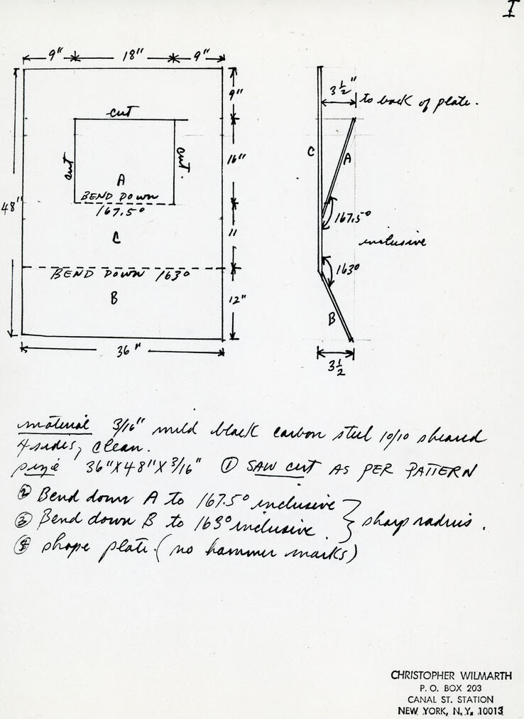
This image is a technical drawing and instruction sheet created by Christopher Wilmarth for a metalworking project. The drawing contains precise measurements, diagrams, and written instructions for shaping a steel plate.
Key Features:
Left Diagram (2D Layout with Dimensions):
- A rectangular steel plate measuring 36" × 48" is detailed.
- It has a central section labeled “A” that is cut and bent down at an angle of 167.5°.
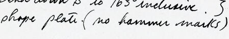
- Additional sections labeled “B” and “C” are also cut and bent, with section “B” bent to an angle of 163°.
- Dimensions such as 9", 18", and 12" are specified for spacings, cuts, and bends, with lines and annotations marking exact locations.
Right Diagram (Side View):
- A profile view shows how sections A and B are bent at their respective angles.
- It includes the specific distances, e.g., 3½" to back of plate, showing the resulting 3D shaping.
Written Instructions (Bottom Section):
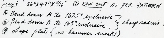
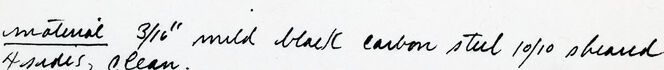
- The material used is "3/16” mild black carbon steel" cut and shaped as per the drawing.
- Three steps are listed:
- Step 1: Bend section A to 167.5° inclusive.
- Step 2: Bend section B to 163° inclusive, ensuring a smooth radius.
- Step 3: Shape the plate carefully, avoiding hammer marks.
Footer:
- Christopher Wilmarth’s signature and contact details are included at the bottom, referencing his studio at Canal Street Station in New York City.
Overall, this image combines precise engineering drawings with artisanal craftsmanship instructions, emphasizing both technical accuracy and aesthetic quality.
Created by gpt-4o-2024-08-06 on 2025-06-12
The image is a hand-drawn technical sketch by Christopher Wilmarth, detailing the specifications for cutting and bending a piece of metal.
On the left side of the image, there is a rectangle marked with various measurements. The outer dimensions are 36 inches wide and 48 inches tall. Inside, two smaller sections, labeled "A" and "B," are marked out with specific measurements for cutting and bending. The sketch specifies cuts at the top corners and indicates bends along horizontal lines within the rectangle, with section "A" bent down at an angle of 167.5 degrees and section "B" at 163 degrees. Section "C" is left unmarked for bending.
On the right side, a side view diagram illustrates the intended angle of each bend, labeling sections "A" and "B" with their respective angles as bent inward, and specifying distances such as "3½ inches to back of plate."
At the bottom, detailed instructions are provided in handwriting, specifying materials and steps for shaping the plate:
- The material should be 3/16" mild black carbon steel, 10/10 sheared, flat, and clean.
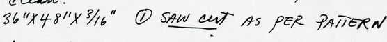
- The dimension "piece" should measure 36" x 48" x 3/16".
- Saw cut as per pattern.
- Bend down "A" to 167.5° inclusive and "B" to 163° inclusive, ensuring to hang the radius.
- Finally, shape the plate with no hammer marks for a clean finish.
At the bottom right corner, Christopher Wilmarth's contact information is provided, including an address at P.O. Box 203, Canal St. Station, New York, N.Y., 10013.
Anthropic Claude
Created by anthropic.claude-3-haiku-20240307-v1:0 on 2025-06-15
This image appears to be a technical drawing or schematic diagram. It contains detailed measurements and instructions for bending and cutting a piece of material, likely metal or steel. The drawing includes specific dimensions and angles, as well as notes about the material and the cutting process. There are no human faces or identifiable individuals present in the image.
Created by us.anthropic.claude-3-5-sonnet-20241022-v2:0 on 2025-06-15
This image shows a technical drawing or blueprint with detailed measurements and bending instructions for what appears to be a metal plate. The main drawing shows a rectangular piece measuring 36" x 48" divided into sections A and B by a dotted line. The right side of the image shows a side view with specific angles for bending.
The specifications include:
- Material: 3/16" mild black carbon steel, 1910 standard
- Overall dimensions: 36" x 48" x 3/16"
- Bend instructions for sections A and B with specific angles (161.5° and 165° respectively)
- Sharp radius requirements
- Notes about plate shaping without hammer marks
The drawing includes precise measurements for various sections and angles, with clear markings for where cuts and bends should be made. The document appears to be a fabrication instruction sheet for metalworking.
At the bottom of the page, there appears to be contact information for an address in New York.
Meta Llama
Created by us.meta.llama3-2-11b-instruct-v1:0 on 2025-06-11
The image presents a hand-drawn diagram and accompanying notes, likely from a technical or instructional context. The diagram is divided into two sections: a rectangular shape on the left and a smaller, angled rectangle on the right. Both sections are labeled with measurements and annotations in black ink.
Left Section:
- A large rectangle with dimensions:
- Height: 18 inches
- Width: 36 inches
- Depth: 12 inches
- A smaller rectangle within the larger one, with dimensions:
- Height: 9 inches
- Width: 18 inches
- Depth: 12 inches
- Annotations:
- "BEND DOWN 167.5°"
- "BEND DOWN 163°"
- "SAW CUT AS PER PATTERN"
Right Section:
- A smaller, angled rectangle with dimensions:
- Height: 9 inches
- Width: 3.5 inches
- Depth: 32 inches
- Annotations:
- "to look of plate."
- "inclusive"
Notes:
- Handwritten notes below the diagram provide additional information:
- "material 3/4" mild black carbon steel 10/10 sheared plates, @lean."
- "36"X48"X3/16" D SAW CUT AS PER PATTERN"
- "Bend down A to 167.5° inclusive."
- "Bend down B to 163° inclusive."
- "Sharp radius."
- "Phosphate plate (no hammer marks)"
Footer:
- A footer at the bottom of the page contains the following information:
- Name: Christopher Wilmarth
- Address: P.O. Box 203, Canal St. Station, New York, N.Y. 10013
In summary, the image appears to be a technical drawing or instruction sheet for a project involving metalworking or fabrication. The diagram and notes provide detailed specifications and instructions for cutting and bending metal plates to achieve a specific shape and pattern.
Created by us.meta.llama3-2-90b-instruct-v1:0 on 2025-06-11
This image depicts a technical drawing of a metal plate, accompanied by handwritten notes and measurements. The drawing is rendered in black ink on white paper, with the plate's dimensions and bend points clearly labeled.
The plate itself is rectangular, measuring 18 inches by 9 inches, with a smaller rectangle cut out from its center. The cut-out rectangle measures 9 inches by 6 inches, leaving a 3-inch border around it. The plate is to be bent down at two points: one at 167.5 degrees, 3/16 of an inch from the top edge, and another at 163 degrees, 3/16 of an inch from the bottom edge.
The handwritten notes provide additional instructions for the fabrication process. They specify that the material should be 3/16-inch mild black carbon steel, 10/10 sheared, and that the plate should be bent down A to 167.5 degrees inclusive and B to 163 degrees inclusive. The notes also mention that the plate should be sheared to size, with no hammer marks.
Overall, this image appears to be a detailed technical drawing for the fabrication of a metal plate, complete with precise measurements and instructions for its construction.
Amazon Nova
Created by amazon.nova-pro-v1:0 on 2025-06-05
The image shows a technical drawing of a steel plate with measurements and instructions for bending. The drawing includes a rectangular shape with dimensions and labels for different sections. The drawing also includes a smaller rectangular shape with measurements and instructions for bending down specific sections. The drawing is labeled with the name "Christopher Wilmarth" and the address "P.O. Box 203 Canal St. Station New York, N.Y. 10013." The drawing appears to be a detailed plan for fabricating a steel plate with specific bends and dimensions.
Created by amazon.nova-lite-v1:0 on 2025-06-05
The image appears to be a technical drawing or blueprint for a metal fabrication project. The drawing shows various dimensions, angles, and instructions for cutting and bending metal plates. Some key details are:
- The material is specified as 3/16" mild black carbon steel, 10/10 shaved.
- There are multiple sections labeled A, B, and C with corresponding bend angles and radii.
- Specific dimensions are given for the cuts and bends, such as 167.5°, 163°, and 163° inclusive.
- The drawing includes instructions for sawing, bending, and shaping the metal plates.
- The author's name, Christopher Wilmarth, and address are provided at the bottom of the image.
Overall, the image appears to be a technical drawing or blueprint for a metal fabrication project, providing detailed instructions for cutting, bending, and shaping metal plates to specific dimensions and angles. The drawing includes dimensions, angles, and specific instructions for the fabrication process.
Google Gemini
Created by gemini-2.0-flash on 2025-05-08
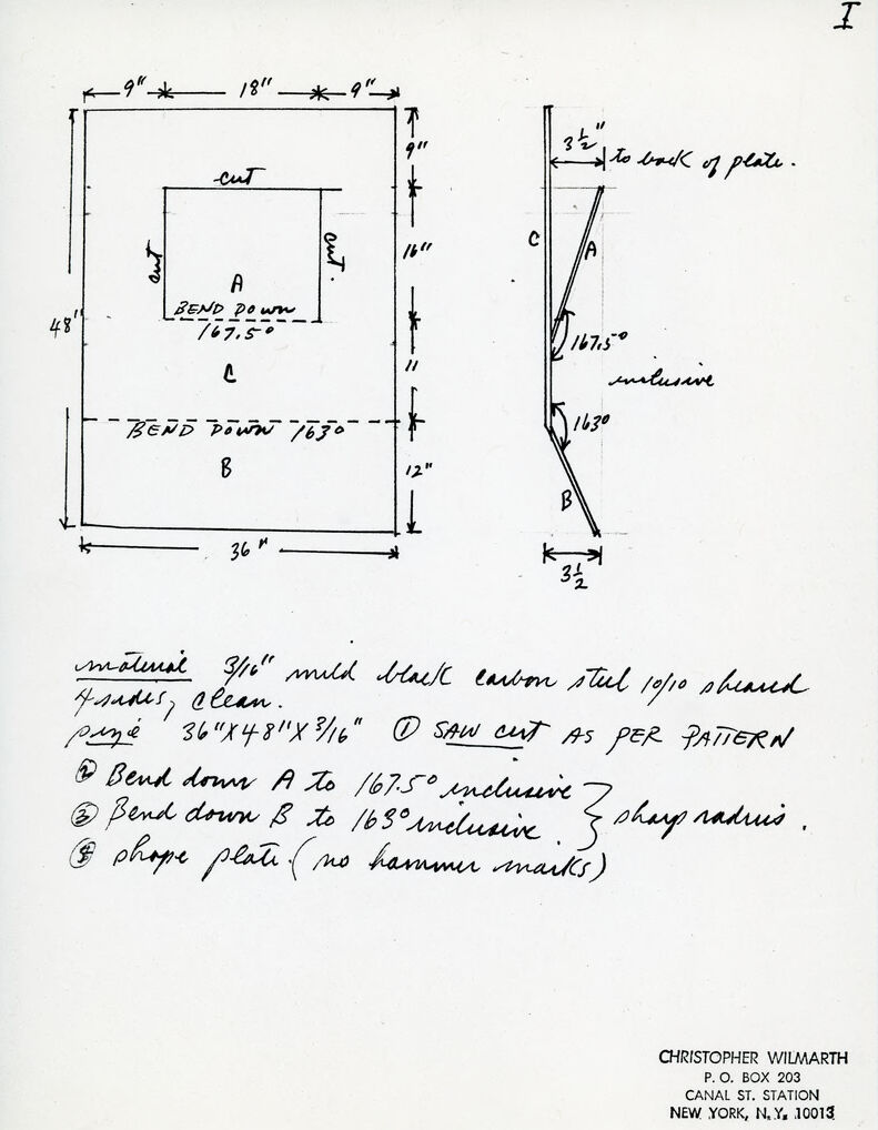
The image contains a technical drawing and notes for a metal fabrication project. The drawing presents two views of the piece: a frontal view with dimensions and cut lines, and a side view showing the bends and angles.
In the frontal view, a rectangular piece of material is depicted with overall dimensions of 36" x 48". There is a rectangular cutout labeled "A" with "BEND DOWN 167.5°" written underneath. The area below the cutout is labeled "C", and there is another bend line near the bottom labeled "BEND DOWN 1630" with the area below designated as "B". Dimensions such as 9", 18", 16", 11", and 12" are noted along the edges. Cut lines are indicated with the word "cut" next to them.
The side view shows the piece's profile after the bends. It includes the angles of the bends (167.5° and 163°) and the distance from the front of the piece to the back of the plate, which is noted as 3½".
Below the drawings, handwritten notes specify the material as "3/16" mild black carbon steel 10/10 sheared" and the plate size as "36" x 48" x 3/16"". The notes outline the fabrication steps, including cutting as per the pattern, bending down areas A and B to the specified angles with a "sharp radius", and shaping the plate without hammer marks.
Finally, the image includes contact information for "CHRISTOPHER WILMARTH" at "P.O. BOX 203, CANAL ST. STATION, NEW YORK, NY, 10013". The drawing is labeled as "I" in the top right corner.
Created by gemini-2.0-flash-lite on 2025-05-08
This image is a technical drawing, likely a blueprint or a set of instructions for fabricating a metal object. It's hand-drawn, likely from the late 20th century, and features several key elements:
Main Components:
- Plan View (Left): Shows a flat, unfolded view of the metal sheet. It's a rectangle with a smaller rectangular cutout in the center. Dimensions are given for the overall size (36" x 48") and the placement of the cutout (18" x 9"). Lines labeled "cut" indicate where material should be removed.
- Side View (Right): Shows a profile view of the finished, bent object. It illustrates the angles and shapes created by bending the metal. The views are labeled with letters A, B, and C, corresponding to the sections of the metal sheet.
- Text Annotations: The drawing is accompanied by handwritten notes providing additional instructions. The instructions include:
- Material specifications: 3/16" mild black carbon steel, 10/10 sheared.
- Dimensions: 36"x48"x3/16"
- Fabrication steps: "Saw cut as per pattern", bend down section A to 167.5° inclusive and bend down section B to 163° inclusive. It also states "shape plate (no hammer marks)."
Geometric Information:
- Angles are specified for the bends: 167.5° (at A) and 163° (at B), with the terms "inclusive" next to the angle.
- Dimensions are provided, including overall length, width, and locations of cuts and bends.
Organization and Style:
- The drawing is neat, but the handwriting gives it a personal touch, indicating it was likely made by an individual.
- The dimensions and angles are clearly labeled for the fabricator.
Additional details:
- The text specifies that the cutting is done according to a separate pattern, implying there's another reference drawing or template.
- The instructions mention a sharp radius, specifying the bend type.
- A section of the annotation reads, "shape plate (no hammer marks)," indicating the desired finish quality.
Conclusion:
Overall, this image is a practical set of instructions designed for someone to fabricate a metal piece with specific bends and angles. It is a testament to hands-on design and the creation of things.
Mistral Pixtral
Created by us.mistral.pixtral-large-2502-v1:0 on 2025-06-02
The image is a technical drawing with specifications for fabricating a metal part. Here is a detailed summary:
Material Specifications:
- Material: 3/16" mild black carbon steel
- Finish: 10/10 sheared, clean
- Size: 36" x 48" x 3/16"
Fabrication Instructions:
Cutting:
- Saw cut as per the pattern indicated in the drawing.
Bending:
- Bend A: Bend down to 167.5° inclusive.
- Bend B: Bend down to 168° inclusive.
- Ensure a sharp radius for Bend B.
Finishing:
- Shape plate (no hammer marks).
Dimensions and Bends:
- The overall dimensions of the part are 36" x 48" x 3/16".
- The part has two main bends:
- Bend A: At 167.5°, located 18" from the top and 9" from the sides.
- Bend B: At 168°, located 12" from the bottom and 32" from the sides.
Additional Notes:
- The drawing includes a side view showing the angles and positions of the bends.
- The part should be bent downwards at the specified angles.
- The material should be clean and free of hammer marks after shaping.
Contact Information:
- Name: Christopher Wilmarth
- Address: P.O. Box 203, Canal St. Station, New York, N.Y. 10013
This detailed drawing provides clear instructions for cutting, bending, and finishing a specific metal part.
Qwen
No captions written
Text analysis
Amazon