Machine Generated Data
Tags
Color Analysis
Feature analysis
Amazon
Clarifai

Clarifai
| Envelope | 54.4% | |
Categories
Imagga
created on 2018-05-08
| text visuals | 99.9% | |
Captions
Microsoft
created by unknown on 2018-05-08
| a close up of text on a white background | 67.5% | |
| a close up of text on a black background | 60.8% | |
| a close up of text on a white surface | 60.7% | |
Clarifai
No captions written
Salesforce
Created by general-english-image-caption-blip on 2025-05-15
a photograph of a map of a map of a map of a city
Created by general-english-image-caption-blip-2 on 2025-07-06
a handwritten map of the area with a note on it
OpenAI GPT
Created by gpt-4o-2024-11-20 on 2025-06-13
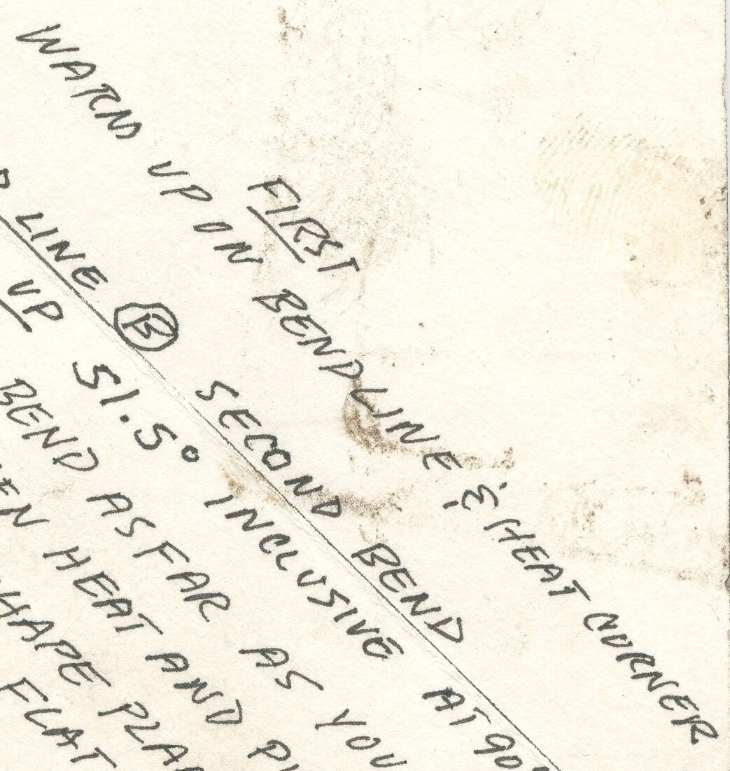
This image appears to be a hand-drawn sheet showing notes and instructions related to metalworking, fabrication, or bending operations. The drawing includes dimensions, bend lines, and annotations for performing specific tasks.
Layout and Dimensions:
- The sheet has a rectangular shape with marked dimensions: 30 inches on the shorter sides and 60 inches on one longer side.
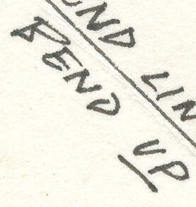
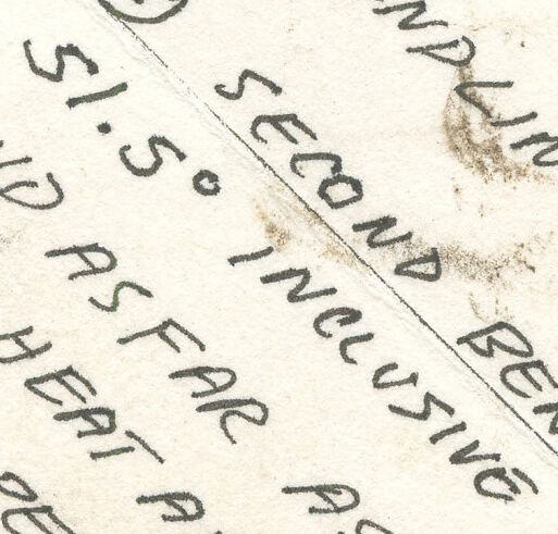
- A diagonal line labeled "Cut (Completed)" divides the rectangle into two triangular sections.
Bend Instructions:
- First Bend:
- It is labeled "Bend Line (A)."
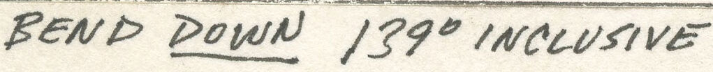
- Instruction states to bend down to a 139° inclusive angle at 90° to the bend line using "Vise 5."
- A note advises using a "Sharp Upper Die."
- Second Bend:
- Labeled "Bend Line (B)."
- Instruction asks to bend up to 51.5° inclusive angle at 90° to the bend line.
- A cautionary note reads: "Watch up on bending / heat corners."
- Additional guidance suggests bending as far as possible, then heating and pulling the shape into a flat configuration.
- First Bend:
Annotations:
- Handwritten notes provide supplemental details regarding angles, tooling, and processes.
- Other faint markings suggest wear and tear from use or reference.
This image seems to be part of a manufacturing or workshop instruction for crafting a specific piece or component, likely involving shaping or bending metal.
Created by gpt-4o-2024-08-06 on 2025-06-13
The image shows a hand-drawn diagram with instructions related to bending a piece of material. The diagram features lines with various annotations and measurements written in pencil.
In the top left corner, it shows a measurement of "30°" and "30°" along two lines that form a right angle. Below this, another measurement "60°" is noted.
At the intersection of two lines, there are instructions:
- "BEND LINE (A) FIRST BEND"
- "BEND DOWN 139° INCLUSIVE AT 90° TO BEND LINE"
- "USE 5 USE SHARP UPPER DIE"
Further instructions angled toward the lower right:
- "WATCH UP ON BEND LINE A"
- "BEND LINE B SECOND BEND"
- "BEND UP 51.5° INCLUSIVE AT 90° TO BEND LINE"
- "BEND AS FAR AS YOU CAN THEN HEAT AND PULL SHARP FLANGE FLAT"
The diagram suggests how to perform bending operations, considering angles and the need for heating to aid the bending process. The instructions are spread across the diagram, with some lines marked as "cut (completed)" indicating stages or completed aspects of a fabrication process.
The image has some smudges and marks that may indicate use in a workshop or engineering environment.
Anthropic Claude
Created by anthropic.claude-3-haiku-20240307-v1:0 on 2025-06-16
The image appears to be a technical drawing or diagram, likely related to engineering or construction. It contains various measurements, instructions, and annotations. The main focus seems to be on a "bend line" and instructions for bending or shaping a material at a specific angle. The image also includes notes about using a "sharp upper die" and other technical details. Overall, this appears to be a detailed technical reference or guide for a specific manufacturing or construction process.
Created by us.anthropic.claude-3-opus-20240229-v1:0 on 2025-06-16
The image shows a sketch or diagram drawn on an old, weathered piece of paper. The diagram depicts how to bend a line at a 90 degree angle to make a sharp turn. There are handwritten notes and measurements around the diagram providing instructions, such as "Bend line @ first bend", "Bend down 139° inclusive", and "Use sharp upper die". The paper has fold marks and appears aged and worn.
Created by us.anthropic.claude-3-5-sonnet-20241022-v2:0 on 2025-06-16
This appears to be a technical drawing or diagram showing bending instructions. The image shows measurements and specifications for making bends in what seems to be sheet metal or similar material. Key details include:
- "BEND LINE (A) FIRST BEND"
- "BEND DOWN 139° INCLUSIVE AT 90° TO BENDLINE"
- "USE SHARP UPPER DIE"
The drawing includes some angular measurements and appears to be marked with dimensions of "30" and "60" (possibly inches). There are also some handwritten notes and instructions regarding the bending process. The document has a somewhat aged or vintage appearance, with slight discoloration and wear visible on the paper.
Meta Llama
Created by us.meta.llama3-2-11b-instruct-v1:0 on 2025-06-12
The image presents a hand-drawn diagram on a piece of paper, likely used for instructional or reference purposes. The diagram is divided into two sections by a vertical line, with the left side featuring a series of handwritten notes and the right side containing additional text and diagrams.
Left Section:
- The top-left corner displays the text "BEND LINE A FIRST BEND" in black ink.
- Below this, the text "BEND DOWN 139° INCLUSIVE AT 90° TO BEND LINE" is written, followed by "USE SHARP UPPER DIE".
- Further down, the text "USE SHARP UPPER DIE" is repeated.
Right Section:
- The top-right corner features the text "CUT (COMPLETED)" in black ink.
- Below this, the text "WARM UP ON BEND LINE & HEAT CARRIER" is written, followed by "BEND LINE A FIRST BEND UP 51.5° INCLUSIVE AT 90° TO BEND".
- The next line reads "THEN HEAT AND PULL SHAPE PLANES FLAT".
- The final line states "SECOND BEND AT 90° TO BEND".
Additional Text:
- In the bottom-right corner, the text "60"" is written in black ink.
- In the top-right corner, the text "30" is written twice, once above and once below the vertical line.
Overall:
The diagram appears to be a detailed guide for a specific manufacturing or crafting process, likely involving metalworking or bending. The use of technical terms and precise measurements suggests that the diagram is intended for professionals or experienced individuals. The diagram's purpose is to provide clear instructions and visual aids for completing a complex task.
Created by us.meta.llama3-2-90b-instruct-v1:0 on 2025-06-12
This image appears to be a page from a notebook or manual, featuring handwritten notes and diagrams related to bending metal. The page is divided into two sections by a vertical line, with the left side containing text and the right side displaying a diagram.
The text on the left side includes instructions for bending metal, such as "BEND LINE A FIRST BEND" and "USE SHARP UPPER DIE." The diagram on the right side shows a series of lines and angles, likely representing the bending process. The background of the page is a light beige color, with some stains and smudges visible.
Overall, this image suggests that the page is part of a guide or tutorial for working with metal, providing step-by-step instructions and visual aids to help users understand the bending process.
Amazon Nova
Created by amazon.nova-lite-v1:0 on 2025-06-10
The image is a faded, aged document with handwritten instructions. It appears to be a technical guide or manual, likely used for manufacturing or crafting purposes. The document is divided into four sections, each with different measurements and instructions. The top left section has the measurement "30" and the instruction "BEND LINE (A) FIRST BEND." The top right section has the measurement "30" and the instruction "CUT COMPLETED." The bottom left section has the measurement "60" and the instruction "BEND DOWN 1390 INCLUSIVE USE 5 AT 90° TO BENDLINE USE SHARP UPPER DIE." The bottom right section has the measurement "60" and the instruction "BEND LINE UP @ 60° TO REVERSE." The document is filled with technical jargon and abbreviations, suggesting that it is intended for a specific audience with knowledge of the subject matter.
Created by amazon.nova-pro-v1:0 on 2025-06-10
The image depicts a piece of paper that is folded into a triangle. The paper has a light beige color and appears to be old, with visible creases and slight discoloration. The paper is divided into two sections by a central vertical crease. The left section contains several handwritten instructions and notes in black ink. The text includes phrases such as "BEND LINE," "FIRST BEND," "BEND DOWN 1390 INCLUSIVE," "USE AT 90° TO BENDLINE," "USE SHARP UPPER DIE," and "60". The right section of the paper has additional handwritten text and notes, which are less legible and seem to provide further instructions or explanations. The overall appearance suggests that the paper is a manual or guide for a specific process, possibly related to bending or shaping materials.
Google Gemini
Created by gemini-2.0-flash on 2025-05-21
Here is a description of the image:
The image is a hand-drawn diagram or sketch, likely a set of instructions for bending a piece of material (possibly metal). It appears to be a design blueprint.
The diagram includes dimensions (30" and 60") marked along the edges. There are two bend lines labeled "Bend Line A" for the first bend and "Bend Line B" for the second bend.
The instructions specify:
- "Bend Line A": First Bend, bend down 139° inclusive, at 90° to bend line. It also states "Use Sharp Upper Die."
- "Cut (Completed)" at the intersection of the vertical and horizontal lines.
- "Bend Line B": Second Bend, bend up 51.5° inclusive at 90° to bend line. It also instructs to "Warm up on bend line & heat corner" and to "Bend as far as you can, then heat and pull shape planes flat."
The image has a hand-drawn quality with handwritten notes indicating the process and desired outcome of the bends.
Created by gemini-2.0-flash-lite on 2025-05-21
Here's a description of the image:
The image is a hand-drawn diagram with instructions for bending a piece of sheet metal. The diagram appears to be a simple illustration on a sheet of paper, possibly a blueprint or a work order.
Key Features:
- Dimensions: The diagram is labeled with measurements in inches ("30", "60"). The dimensions appear to define the overall size or shape of the metal piece.
- Bend Lines: There are several lines labeled as "Bend Line A" (First Bend) and "Bend Line B" (Second Bend). These lines likely indicate where the metal needs to be bent.
- Bend Instructions: The diagram provides detailed instructions for each bend:
- "Bend Line A" instructions include:
- "Bend Down 139° Inclusive"
- "Use S" (likely referring to a specific tool or die)
- "At 90° to Bend Line"
- "Use Sharp Upper Die"
- "Bend Line B" instructions include:
- "Bend Up 51.5° Inclusive"
- "Bend as far as you can"
- "Then Heat and Pull"
- "Shape Planes Flat"
- "Bend Line A" instructions include:
- Other Notes: The diagram also includes notations like "Cut (Completed)" to mark a completed process, "Warm up on bendline & heat corner", to clarify other points in the process.
Overall, the image is a technical diagram likely used in a metal fabrication shop. It guides the user through a series of bends and processes to achieve a specific shape or form for a piece of metal.
Mistral Pixtral
Created by us.mistral.pixtral-large-2502-v1:0 on 2025-06-03
The image appears to be a hand-drawn diagram with instructions for bending a piece of material, likely metal, into a specific shape. Here is a detailed summary of the instructions and diagram:
Dimensions:
- The material is a rectangle with dimensions 60 inches by 50 inches.
- There is a cut line at 30 inches along the 60-inch side, dividing the material into two sections: 30 inches and 30 inches.
Bend Lines and Instructions:
- First Bend:
- Bend Line @: The first bend is made along a line that is 25 inches from the left edge and 30 inches from the top edge.
- Bend down 139 degrees inclusive at 90 degrees to the bend line.
- Use a sharp upper die (tool) for this bend.
- Use 5 (possibly referring to a specific tool or setting).
- Second Bend:
- Bend Line @: The second bend is made along a line that is 51.5 inches from the left edge and at 90 degrees to the first bend line.
- Warm up the bend line and heat the corner at 90 degrees to the bend line.
- Bend up as far as you can and pull.
- Bend and shape the planes flat.
- First Bend:
Additional Notes:
- The diagram includes arrows and lines to indicate the direction and location of the bends.
- The term "USE SHARP UPPER DIE" suggests the use of a specific tool for the bending process.
- The instructions emphasize heating and shaping the material to achieve the desired bend.
Overall, the diagram provides a step-by-step guide for bending a rectangular piece of material into a specific shape, with detailed instructions on where to make the bends and how to execute them.
Qwen
No captions written
Text analysis
Amazon