Machine Generated Data
Tags
Color Analysis
Feature analysis
Amazon
Clarifai

Clarifai
| Envelope | 33.9% | |
Categories
Imagga
created on 2019-03-25
| text visuals | 99.8% | |
Captions
Microsoft
created by unknown on 2019-03-25
| a close up of text on a white background | 73.3% | |
| a close up of text on a black background | 67.6% | |
| a close up of text on a white surface | 67.5% | |
Clarifai
Created by general-english-image-caption-clip on 2025-07-11
a diagram of the experimental apparatus.
Salesforce
Created by general-english-image-caption-blip on 2025-05-23
a photograph of a drawing of a drawing of a kitchen
OpenAI GPT
Created by gpt-4o-2024-11-20 on 2025-06-13
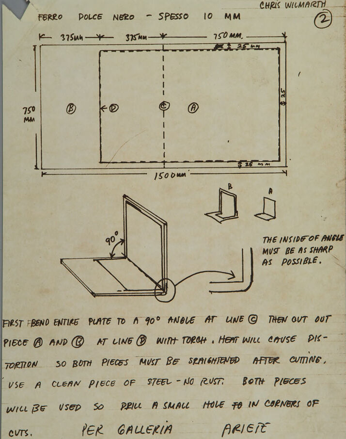
This image depicts a hand-drawn technical diagram or instruction sketch for fabricating a steel structure, likely intended for art or construction purposes. The notes and annotations appear to be written by Chris Wilmarth, as indicated at the top right of the page.
Main Elements and Structure:
Rectangular Steel Plate:
- A large rectangular plate is divided into smaller segments with dimensions provided:
- The overall size is 1500 mm (width) by 750 mm (height).
- Horizontal divisions of 375 mm for segments labeled as "B" and "A," with "C" and "D" located centrally.
- Edges are marked with a thickness of 25 mm.
- A large rectangular plate is divided into smaller segments with dimensions provided:
Bending Plan:
- Accompanying sketches depict a process to bend the steel plate along line C at a 90-degree angle.
- The angle is noted to require a sharp inside corner.
Individual Part Extraction:
- Instructions specify cutting out pieces A and B at line D using a torch. Cutting is noted to cause distortion, necessitating straightening afterward.
Additional Notes:
- The steel plate should be clean and rust-free.
- Small holes must be drilled in the corners of cuts for use in the fabrication process.
- The text suggests these pieces are intended for an exhibition ("Per Galleria Ariete").
Text Instructions:
- The process involves bending, cutting, and ensuring precise reshaping of steel pieces. The goal is to create sharp edges and accurate dimensions during fabrication.
Created by gpt-4o-2024-08-06 on 2025-06-13
The image is a hand-drawn technical sketch or blueprint by Chris Wilmarth, likely intended for the creation of a metal sculpture or structure. It is labeled "2" in the upper right corner, suggesting it is part of a series. The drawing includes a large rectangle with dimensions labeled as 1500 mm by 750 mm, divided into sections with further length measurements of 375 mm, 375 mm, and 750 mm. Each section is labeled with letters: (B), (C), (A), and (D). The thickness of the material is specified as 10 mm, with the words "Ferro Dolce Nero - Spesso 10 MM" indicating a type of soft black iron.
A smaller inset sketch illustrates how part of this plate is to be bent at a 90° angle along line C. The rectangles labeled B and A appear to represent the bent sections of the metal, positioned vertically from a horizontal base.
The instructions written on the sketch provide a step-by-step guide to the fabrication process:
- Bend the entire plate to a 90° angle at line (C).
- Cut out piece (A) and (B) at line (D) with a torch, noting that the heat will cause distortion, requiring both pieces to be straightened post-cutting.
- Use clean, rust-free steel.
- Drill a small hole in the corners of the cuts.
The text emphasizes that the inside of the angles must be sharp and precise, and that both pieces will be used. At the bottom, the words "PER GALLERIA ARIETE" are written, indicating that this piece may be intended for display at Galleria Ariete, a possible name of a gallery or exhibition space.
Anthropic Claude
Created by anthropic.claude-3-haiku-20240307-v1:0 on 2025-06-20
The image appears to be a technical drawing or instructions for creating a metal frame or structure. It includes detailed measurements, angles, and steps for bending and shaping the metal pieces. The instructions emphasize the importance of ensuring the edges are sharp and the pieces are straightened after cutting. The drawing also includes a note about using a clean piece of steel with no rust. Overall, the image seems to be providing detailed guidance for fabricating a specific metal object or component.
Created by us.anthropic.claude-3-5-sonnet-20241022-v2:0 on 2025-06-20
This is a technical drawing or blueprint showing fabrication instructions for what appears to be a metal plate construction. The drawing includes measurements in millimeters, with dimensions of 1500mm in length and 750mm in height. The title at the top indicates "FERRO DOLCE NEBO - SPESSO 10 MM."
The diagram shows both a top-down view of the plate with labeled points (B, D, C) and a series of smaller sketches below demonstrating how the piece should be bent at a 90-degree angle. There are specific instructions noting that "THE INSIDE OF ANGLE MUST BE AS SHARP AS POSSIBLE."
The written instructions detail the bending and cutting process, mentioning that heat from a torch will cause distortion and the pieces must be straightened after cutting. It specifies to use clean steel with no rust and to drill small holes in the corners of cuts.
At the bottom, there's a notation "PER GALLERIA ARIETE" suggesting this might be for an art gallery installation or display. The drawing appears to be labeled as #2, possibly part of a larger set of fabrication instructions.
Meta Llama
Created by us.meta.llama3-2-11b-instruct-v1:0 on 2025-06-10
The image shows a hand-drawn diagram of a metal plate with a hole cut out of it, along with some handwritten notes. The diagram is drawn on a piece of paper that appears to be aged or stained.
- The diagram shows a rectangular metal plate with a hole cut out of it, and some measurements are written above and below the diagram.
- The measurements include the width and height of the plate, as well as the diameter of the hole.
- The measurements are written in millimeters.
- Below the diagram, there are some handwritten notes that provide additional information about the plate and the hole.
- The notes include instructions for cutting the hole, such as using a clean piece of steel and drilling a small hole in the corners of cuts.
- The notes also mention that the inside of the angle must be as sharp as possible.
- In the top-right corner of the page, there is a signature that reads "Chris Wilmarth".
- The signature suggests that the diagram was created by Chris Wilmarth, who may be an engineer or designer.
- In the bottom-left corner of the page, there is a note that reads "Per Galleria Ariete".
- The note suggests that the diagram was created for a gallery called Ariete, which may be a art gallery or a design studio.
Overall, the image appears to be a technical drawing of a metal plate with a hole cut out of it, along with some notes and instructions for cutting the hole. The diagram and notes suggest that the plate was designed for a specific purpose, such as a piece of art or a functional object.
Created by us.meta.llama3-2-90b-instruct-v1:0 on 2025-06-10
The image is a hand-drawn diagram of a metal plate, accompanied by instructions for bending and cutting it. The diagram is drawn on a piece of paper with a light brown color and features black ink markings.
Diagram:
- The diagram shows a rectangular metal plate with dimensions labeled in millimeters.
- The plate has a length of 1500 mm and a width of 750 mm.
- There are two lines drawn on the plate, one at 375 mm from the top edge and another at 375 mm from the bottom edge.
- The lines are labeled "A" and "B," respectively.
- There is a small circle drawn at the intersection of the two lines, labeled "C."
- The diagram also includes a scale drawing of the plate, showing its thickness and the location of the bend lines.
Instructions:
- The instructions are written in black ink below the diagram.
- They provide step-by-step guidance on how to bend and cut the metal plate.
- The instructions include information on the tools required, such as a torch and a drill press.
- They also specify the angle at which the plate should be bent and the location of the cuts.
Additional Information:
- The image includes additional information, such as the name of the person who created the diagram (Chris Wilmarth) and the date it was created (February 2).
- There is also a note at the bottom of the image that reads, "Per Galleria Ariete."
Amazon Nova
Created by amazon.nova-lite-v1:0 on 2025-06-08
The image appears to be a technical drawing or blueprint for a metalworking project. It shows a rectangular piece of metal, with measurements and annotations indicating the dimensions and bending instructions. The drawing includes a table with various measurements and labels, such as "FERO DOLCE NERO - SPESSO 10 MM" and "CHRIS WILMARTH." The drawing also includes a diagram of a metal plate being bent at a 90-degree angle, with instructions on how to achieve a sharp inside angle. The drawing is labeled "Per Galleria Ariete," which may indicate the intended use or purpose of the metalworking project.
Created by amazon.nova-pro-v1:0 on 2025-06-08
The image is a technical drawing of a metal sheet with specific dimensions and instructions for bending and cutting. The sheet is marked with various measurements and annotations.
The top section of the image includes a rectangular frame with dimensions labeled as follows:
- The length of the rectangle is 750 mm.
- The width is 375 mm.
- There is an additional 25 mm added to the width on the right side.
- The total width, including the additional 25 mm, is 375 mm + 25 mm = 400 mm.
Within this frame, there are two vertical lines dividing it into three sections. The central section has a width of 150 mm, and the two outer sections each have a width of 125 mm. The height of the entire frame is 750 mm.
Below the frame, there is a detailed drawing of a metal sheet that has been bent and cut. The drawing shows a 90-degree bend in the metal sheet. The instructions for this process are as follows:
- Bend the entire plate to a 90-degree angle at line C.
- Cut out pieces A and B at line B using a torch.
- Heat will cause distortion, so both pieces must be straightened after cutting.
- Use a clean piece of steel with no rust.
- Both pieces will be used, so drill a small hole in the corners of the cuts.
The image also includes a note that reads "PER GALLERIA ARIEIT," which could be a reference to a specific gallery or project named "ARIEIT."
The drawing is somewhat aged, with visible creases and marks, suggesting it has been handled and possibly used for a long time. The annotations and instructions are handwritten, indicating a manual process for the creation and use of this technical drawing.
Google Gemini
Created by gemini-2.0-flash-lite on 2025-05-16
Here's a description of the image:
The image is a technical drawing or sketch, likely a blueprint for a metal fabrication project. It is drawn on aged or yellowed paper, suggesting it's an older document. The handwriting is in black ink.
Here's a breakdown of the key elements:
Title and Dimensions: The top of the drawing includes Italian words like "FERRO DOLCE NERO - SPESSO 10 MM," which translate to "Mild Black Iron - Thickness 10 mm". It specifies dimensions like 750 mm and 1500 mm, along with other measurements.
Plan View: The primary part of the drawing shows a rectangular shape with internal lines and markings. This appears to be a top-down view of the metal plate before any bending or cutting. Dotted lines are also present.
Isometric view and instructions: Below the rectangle is an isometric (3D-like) view that shows the metal plate bent at a 90-degree angle. Arrows and a note ("THE INSIDE OF ANGLE MUST BE AS SHARP AS POSSIBLE.") indicate the desired outcome. There are also small sketches of the finished project.
Cutting and fabrication instructions: The drawing includes handwritten instructions. The text outlines the fabrication process.
Artist's Name and Date: The upper-right corner contains the name "CHRIS WILMARTH" and the number "(2)", which may be a reference to the revision or part number.
In summary, the image provides step-by-step instructions for cutting, bending, and fabricating a metal component. It likely outlines how to create a structural element.
Created by gemini-2.0-flash on 2025-06-16
The image contains a hand-drawn sketch with instructions for fabricating a metal object. At the top is a rectangular layout with dimensions labeled (1500mm x 750mm), along with dashed cut lines and indicated bending points. Below this are perspective drawings illustrating the bending process and the final shape of two pieces labeled A and B. Accompanying text provides instructions for bending the metal sheet at a 90-degree angle, cutting out pieces, straightening the metal after cutting due to heat distortion, and using clean steel. The sketch is attributed to Chris Wilmarth and notes the project is for "PER GALLERIA ARIETE."
Mistral Pixtral
Created by us.mistral.pixtral-large-2502-v1:0 on 2025-06-03
The image is a hand-drawn technical sketch with instructions for fabricating a metal piece. Here is a detailed summary:
Title and Material Specifications:
- Title: The sketch is titled "Ferro Dolce Nero - Spesso 10 MM," which translates to "Mild Steel - Thickness 10 MM."
- Creator: The sketch is created by Chris Wilmarth.
Dimensions and Layout:
- The main piece is a rectangular plate with the following dimensions:
- Length: 1500 mm
- Width: 750 mm
- Thickness: 10 mm
- There are specific measurements marked on the plate:
- 375 mm from each shorter side (left and right)
- 250 mm from the bottom
- 35 mm from the top right corner
Cutting and Bending Instructions:
Initial Bend:
- Bend the entire plate to a 90-degree angle along line (C).
Cutting:
- Cut out pieces (A) and (B) along line (B) using a torch.
- Note: The heat from the torch will cause distortion, so both pieces must be straightened after cutting.
Material Condition:
- Use a clean piece of steel with no rust.
- Both pieces will be used, so drill a small hole in the corners of the cuts.
Additional Notes:
- The inside of the angle must be as sharp as possible.
- The sketch includes a note at the bottom: "Per Galleria Ariete," which translates to "For Gallery Ariete."
Visual Aids:
- The sketch includes a diagram showing the 90-degree bend and the positions of pieces (A) and (B).
- There is a detailed view of the sharp angle required for the bend.
This sketch provides clear instructions for fabricating a specific metal piece, including dimensions, bending, cutting, and material requirements.
Qwen
Created by Qwen/Qwen2.5-VL-7B-Instruct on 2025-07-24
The image appears to be a technical drawing or blueprint, possibly for a piece of furniture, a metal structure, or an architectural element. Here's a detailed description:
Title and Reference: The top of the document is labeled "FERRO DOLCE NERO - SPESO 10 MM" and has a reference number "2" in a circle, attributed to "CHRIS WILMARTH."
Main Drawing:
- The main drawing is a rectangular layout with measurements in millimeters. The dimensions are as follows:
- The overall width is 1500 mm.
- The height is 750 mm.
- The top and bottom edges are 25 mm wide.
- The left and right edges are 20 mm wide.
- Four sub-sections (A, B, C, D) are indicated within the rectangle, with specific measurements:
- A: 1500 mm (length).
- B: 750 mm (width).
- D: 375 mm (width).
- C: 375 mm (width).
- There is a dashed vertical line dividing the rectangle into two equal parts.
- The main drawing is a rectangular layout with measurements in millimeters. The dimensions are as follows:
Additional Drawings:
- Below the main drawing, there are two additional sketches:
- One shows a section of the rectangular structure with a 90° angle, labeled with annotations for angles and measurements.
- The other shows an exploded view of the structure, suggesting how the pieces fit together.
- Below the main drawing, there are two additional sketches:
Instructions:
- Text below the drawings provides instructions for assembling the piece:
- "FIRST BEND ENTIRE PLATE TO A 90° ANGLE AT LINE C."
- "THEN OUT OUT PIECE A AND B AT LINE D WITH TORCH. HEAT WILL CAUSE DISTORTION SO BOTH PIECES MUST BE STRAIGHTENED AFTER CUTTING."
- "USE A CLEAN PIECE OF STEEL - NO RUST. BOTH PIECES WILL BE USED SO DRILL A SMALL HOLE TO IN CORNERS OF CUTS."
- "PER GALLERIA ARIETE."
- Text below the drawings provides instructions for assembling the piece:
The document appears to be a detailed guide for crafting a specific metal structure, possibly for a piece of furniture or an architectural element, with precise measurements and instructions for construction.
Created by Qwen/Qwen2.5-VL-72B-Instruct on 2025-07-24
This image appears to be a hand-drawn technical diagram and instructions for fabricating a metal piece, specifically using a material named "Ferro Dolce Nero" with a thickness of 10 mm. The drawing includes measurements and annotations for cutting and bending the metal plate.
Key Elements of the Diagram:
Measurements and Layout:
- The overall dimensions of the metal plate are 1500 mm by 750 mm.
- The plate is divided into sections labeled A, B, C, and D.
- There are specific dimensions for each section, such as 375 mm and 750 mm.
Cutting and Bending Instructions:
- The instruction states that the entire plate should be bent to a 90° angle at line C.
- Pieces labeled A and B should be cut out at line D using a torch. The heat from the torch will cause some distortion, so both pieces must be straightened after cutting.
- The material should be a clean piece of steel with no rust.
Additional Notes:
- The inside of the angle must be as sharp as possible.
- Both pieces will be used, so small holes should be drilled in the corners of the cuts.
Annotations:
- The diagram includes handwritten notes and arrows to guide the process.
- The name "Chris Wilmart" is written at the top right corner, possibly indicating the person who created the diagram.
- The text "PER GALLERIA ARIEIT" at the bottom suggests that this is for a gallery or exhibition named Arieit.
Overall, this image is a detailed guide for a metalworking project, providing both visual and written instructions for cutting, bending, and finishing the metal piece.
Text analysis
Amazon