Machine Generated Data
Tags
Color Analysis
Feature analysis
Amazon
Clarifai
AWS Rekognition
| Scoreboard | 68.3% | |

Categories
Imagga
created on 2022-06-10
| text visuals | 96.6% | |
| streetview architecture | 1.5% | |
Captions
Microsoft
created by unknown on 2022-06-10
| diagram, engineering drawing | 99.3% | |
Clarifai
No captions written
Salesforce
Created by general-english-image-caption-blip-2 on 2025-07-06
a blueprint of a bridge with a diagram of the structure
Created by general-english-image-caption-blip on 2025-05-04
a photograph of a black and white photo of a black and white photo of a bridge
OpenAI GPT
Created by gpt-4o-2024-11-20 on 2025-06-09
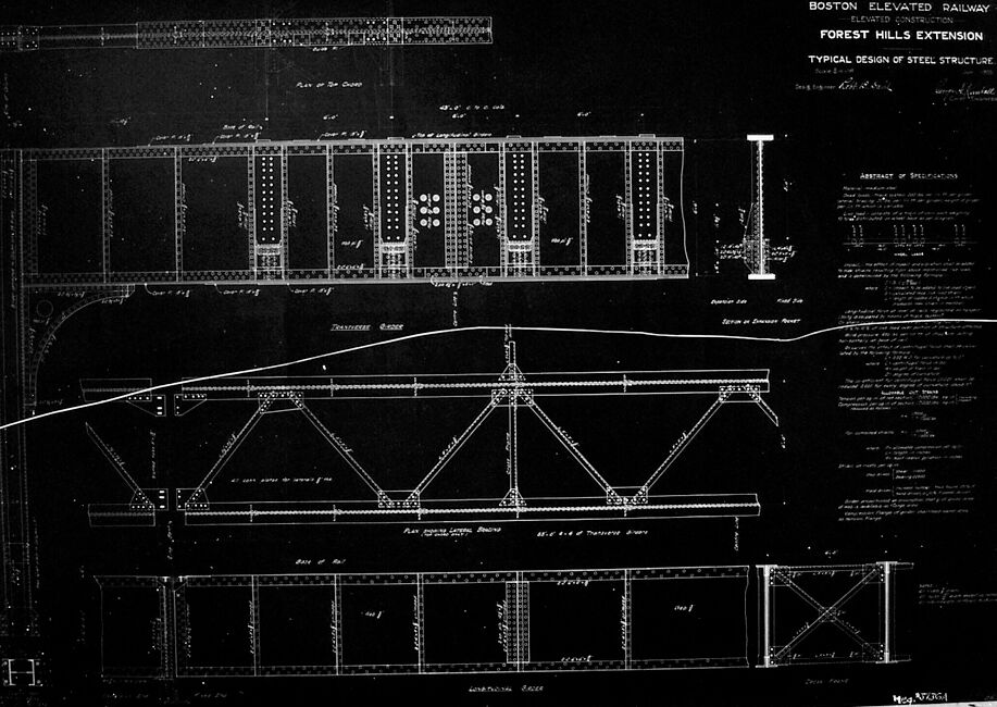
This is a blueprint or technical drawing of a steel structure design for the Boston Elevated Railway's "Forest Hills Extension." The image showcases a detailed plan for an elevated steel construction, including cross-sections, elevations, and framework designs.
The image features:
- Top Section: A detailed elevation view of the steel framework, including vertical support columns and horizontal beams. Measurements and labels describe the dimensions and structural details.
- Middle Section: A triangular truss design is visible, illustrating the load-bearing framework. The trusses are reinforced with diagonal supports and rivet placements clearly marked.
- Bottom Section: Various sectional views of steel girders, trusses, and other components are shown in greater detail. These are labeled with specific notes on their sizes and purposes.
- Text Information: On the right side, there is a column with specifications and notes, labeled "Abstract of Specifications." It includes annotations concerning materials, dimensions, connections, and build instructions.
- Project Title: The top right corner has the project title: Boston Elevated Railway – Forest Hills Extension, with details of the "Typical Design of Steel Structure." There are also references to the consulting engineers and draftsmen involved in the design.
Overall, the image represents an intricate engineering diagram for constructing a segment of the Boston Elevated Railway, focusing heavily on structural integrity and meticulous design documentation.
Created by gpt-4o-2024-08-06 on 2025-06-09
This image is a historical engineering drawing related to the Boston Elevated Railway's Forest Hills Extension. The drawing is a blueprint that depicts the typical design of a steel structure used in the extension project.
In the top left corner, the title reads "Boston Elevated Railway, Elevated Construction, Forest Hills Extension, Typical Design of Steel Structure." The drawing includes detailed plans and elevations for steel beams and trusses, showcasing dimensions, sections, and specifications used in the construction.
Written notes and labels on the plan indicate various parts of the structure, such as "Plan of Top Chord," "Elevation of Truss," and "Section of Decourci Bridge." There is also a section labeled "Abstract of Specifications," which likely lists detailed materials or requirements for the construction.
The blueprint is filled with white lines and text on a dark background, a typical presentation for architectural and engineering drawings of this era. The precision and detail reflect an emphasis on structural integrity and careful planning typical of early 20th-century railway projects.
Anthropic Claude
Created by anthropic.claude-3-haiku-20240307-v1:0 on 2025-06-13
The image appears to be a technical drawing or blueprint for a steel structure, specifically the "Forest Hills Extension" of the Boston Elevated Railway. The drawing shows detailed plans and specifications for the typical design of the steel structure, including cross-sectional views and measurements. The image does not contain any human faces or identities, so I will not attempt to describe or identify any individuals.
Created by us.anthropic.claude-3-opus-20240229-v1:0 on 2025-06-13
The image shows a blueprint or technical drawing of a steel structure, specifically the "Forest Hills Extension" of the Boston Elevated Railway. The drawing depicts the typical design of the steel structure in detail, with measurements and annotations. It includes front, side and aerial views of the structure, showing the arrangement of beams, trusses and supports. The blueprint is dated April 1908 and appears to be signed by the architect or engineer who created it.
Created by us.anthropic.claude-3-5-sonnet-20241022-v2:0 on 2025-06-13
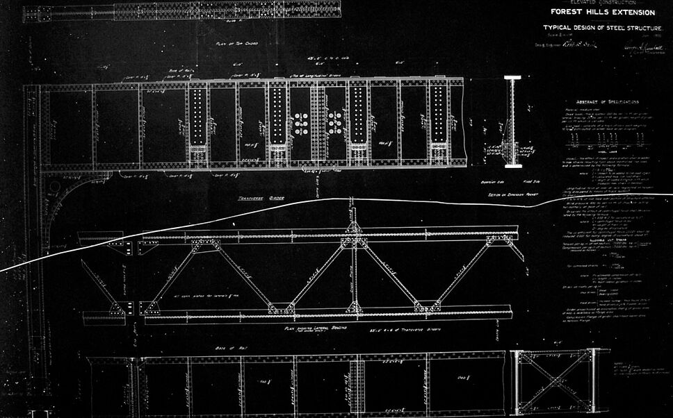
This is a historical engineering blueprint or technical drawing for the Boston Elevated Railway's Forest Hills Extension. The document shows the "Typical Design of Steel Structure" and appears to be a detailed architectural/engineering plan showing multiple views of the elevated railway structure. The drawing includes:
- A top plan view showing the steel framework and support structure
- A side elevation view displaying the truss design with distinctive hexagonal/diamond-shaped support patterns
- Various structural details and measurements
- Technical annotations and notes
The drawing is in the classic blueprint style with white lines on a dark background, which was a common engineering document format in the early 20th century. The level of detail suggests this was likely used for actual construction purposes, showing both the overall design and specific structural elements of the elevated railway system.
Meta Llama
Created by us.meta.llama3-2-90b-instruct-v1:0 on 2025-05-30
This image is a blueprint for the Forest Hills Extension of the Boston Elevated Railway. The blueprint features a black background with white lines and text, showcasing the typical design of steel structure. The top-right corner displays the title "BOSTON ELEVATED RAILWAY FOREST HILLS EXTENSION TYPICAL DESIGN OF STEEL STRUCTURE" in white text.
The blueprint includes various sections, such as a cross-section of the railway, a plan view, and an elevation view. These sections provide detailed information about the steel structure's design, including measurements, materials, and construction methods. The blueprint also features notes and annotations throughout, which likely contain additional information about the project.
Overall, this blueprint provides a comprehensive overview of the Forest Hills Extension's steel structure design, offering valuable insights into the engineering and construction processes involved in building this section of the Boston Elevated Railway.
Created by us.meta.llama3-2-11b-instruct-v1:0 on 2025-05-30
The image is a black-and-white blueprint of the Boston Elevated Railway's Forest Hills Extension, featuring a detailed design of steel structure. The blueprint includes various sections, such as the "Typical Design of Steel Structure" and "FOREST HILLS EXTENSION," with accompanying text that provides additional information about the design.
Key Features:
- Title: "BOSTON ELEVATED RAILWAY FOREST HILLS EXTENSION TYPICAL DESIGN OF STEEL STRUCTURE"
- Blueprint Sections:
- "Typical Design of Steel Structure"
- "FOREST HILLS EXTENSION"
- Text: Provides additional information about the design
- Visuals: A detailed design of steel structure, including various sections and components
- Background: Black-and-white blueprint
Summary:
The image is a detailed blueprint of the Boston Elevated Railway's Forest Hills Extension, showcasing a typical design of steel structure. The blueprint includes various sections and text that provide additional information about the design. The image features a black-and-white background, with white lines and text used to highlight the different components of the design.
Amazon Nova
Created by amazon.nova-lite-v1:0 on 2025-05-28
The image is a black-and-white architectural blueprint for the Boston Elevated Railway Forest Hills Extension. The blueprint includes detailed specifications and diagrams of the steel structure, including measurements and annotations. The blueprint is labeled "Typical Design of Steel Structure" and includes a section labeled "Abstract of Specifications." The blueprint also includes a diagram of the steel structure, showing the layout and dimensions of the structure.
Created by amazon.nova-pro-v1:0 on 2025-05-28
The image is a technical drawing of a steel structure, likely a bridge or a similar construction. The drawing is presented in black and white, with a grid-like background that aids in precision and scale. The structure consists of multiple horizontal beams and vertical supports, forming a repetitive pattern. The beams are connected to the supports with diagonal braces, creating a triangular framework that provides stability. The drawing includes detailed annotations and measurements, indicating the dimensions and specifications of the structure. The text at the top of the image reads "BOSTON ELEVATED RAILWAY ELEVATED CONSTRUCTION FOREST HILLS EXTENSION TYPICAL DESIGN OF STEEL STRUCTURE." This suggests that the drawing is a typical design for a steel structure used in the construction of the Boston Elevated Railway's Forest Hills Extension.
Google Gemini
Created by gemini-2.0-flash-lite on 2025-05-01
The image is a blueprint, most likely an engineering or architectural drawing. It's a detailed technical drawing of a steel structure, probably for a bridge or elevated railway, as indicated by the text "Boston Elevated Railway, Forest Hills Extension, Typical Design of Steel Structure". The blueprint depicts different views and cross-sections of the structure, including plans, elevations, and details of the structural components. It has technical annotations such as dimensions, notes, and specifications, as well as an abstract of specifications. The drawing is in negative, showing the design as white lines on a black background, a typical style for blueprints.
Created by gemini-2.0-flash on 2025-05-01
Here is a description of the image:
The image shows a black-and-white blueprint or technical drawing titled "Boston Elevated Railway, Elevated Construction, Forest Hills Extension: Typical Design of Steel Structure."
The drawing includes various detailed diagrams of structural elements, possibly related to a bridge or elevated railway. There are multiple sections depicting different views and components.
There is also a text block that appears to be an "Abstract of Specifications," detailing technical specifications and requirements for the steel structure.
Mistral Pixtral
Created by us.mistral.pixtral-large-2502-v1:0 on 2025-06-04
The image is a detailed engineering blueprint for the Boston Elevated Railway, specifically for the Forest Hills Extension. The blueprint is titled "Typical Design of Steel Structure" and appears to be dated April 1909.
Key elements of the blueprint include:
Plan View: The top section shows a plan view (top-down view) of the steel structure, detailing the arrangement of the columns, beams, and other structural elements. This section includes labels and dimensions for various components.
Elevation View: The middle section presents an elevation view (side view) of the steel structure, showing how the beams and columns are connected vertically. This view also includes detailed measurements and annotations.
Cross-Sectional Views: The bottom section includes cross-sectional views of the structure, providing a detailed look at the internal arrangement of the beams and columns. These views help in understanding the structural integrity and design.
Abstract of Calculations: On the right side of the blueprint, there is an abstract of calculations, which likely includes mathematical computations and engineering formulas used to determine the structural requirements and load-bearing capacities of the design.
Annotations and Labels: Throughout the blueprint, there are numerous annotations and labels that provide specific details about the materials, dimensions, and connections of the steel structure. These annotations are crucial for the construction and assembly of the structure.
Overall, the blueprint is a comprehensive technical drawing used for the construction of the elevated railway extension, providing all necessary details for the steel structure's design and assembly.
Qwen
Created by Qwen/Qwen2.5-VL-7B-Instruct on 2025-07-11
The image is a detailed blueprint or architectural drawing of a section of the Boston Elevated Railway, specifically the Forest Hills Extension. The drawing is labeled at the top right as "Typical Design of Steel Structure." It depicts a steel structure, likely part of the elevated railway's framework, with various labeled components and measurements.
The drawing includes:
- A top-down view of the steel framework.
- Cross-sectional views at different points, showing the internal structure and connections.
- Annotations and measurements indicating the dimensions and specifications of the steel beams, girders, and other structural elements.
- A key or legend (not fully legible in the image) that likely provides further technical details and component descriptions.
The style of the drawing is typical of technical architectural plans from the early to mid-20th century, with a focus on clarity and precision to facilitate construction. The text and diagrams are neatly organized, with line weights and text sizes designed for easy reading and understanding by engineers and construction workers.
Created by Qwen/Qwen2.5-VL-72B-Instruct on 2025-07-11
This is a black and white blueprint titled "Boston Elevated Railway Forest Hills Extension: Typical Design of Steel Structure." The image shows technical drawings and diagrams of the steel structure for the railway. The blueprint includes various views of the structure, such as top, side, and perspective views, with detailed annotations and measurements. The right side of the image contains text that appears to be an abstract of specifications, providing additional information about the design and construction requirements. The overall layout is organized and meticulously detailed, typical of engineering blueprints.
Text analysis
Amazon